


A portable laser soldering machine is a benchtop or roll-stand laser soldering system — typically 10–100 W diode or fiber laser, closed-loop pyrometer temperature control, and integrated solder wire, paste or ball feedin…
A portable laser soldering machine is a benchtop or roll-stand laser soldering system — typically 10–100 W diode or fiber laser, closed-loop pyrometer temperature control, and integrated solder wire, paste or ball feeding — that can be moved between cells and re-programmed in minutes instead of hours. For small batch production it replaces stencil printing plus reflow with a tooling-free, per-joint heating process: you load a fixture, recall a stored recipe, and solder 20 to 500 units without ordering a stencil, a solder pallet or a reflow profile. The value in low-volume work is changeover time and first-article speed, not throughput.
What does “portable” actually mean in a laser soldering machine — and where does it fit?
In this equipment class, “portable” is a practical description rather than a marketing one. It usually means the machine meets most or all of the following:
- Footprint under ~0.6 m² (roughly 600 × 700 mm table space), so it fits on an ESD bench or a small cart.
- Single-phase 200–240 V supply, 1–2 kW, with a compact air-cooled or small chiller loop — no facility chilled-water drop required.
- Weight 60–120 kg with casters or lifting eyes, so it can be moved between an NPI lab and a pilot line.
- Manual or semi-automatic load: operator places the part in a fixture, vision or a fiducial offset aligns the spot, and the head moves to the stored joint coordinates.
- Recipe library of 100+ programs keyed to part number, so switching from an ECU connector to a sensor flex takes a recall and a fixture swap, not a re-teach.
This class is a good fit for automotive sensor and connector prototypes, optical module builds, medical device electronics with low annual volumes, and semiconductor package-level soldering where the joint count per unit is small but the process window is tight. It is not a substitute for an inline reflow line at volume — the economics only work below roughly a few thousand joints per shift, or where the per-joint heat input must be tightly localised (adjacent temperature-sensitive parts, flex-to-PCB, die-attach on a populated board).
Which specifications decide whether a benchtop laser soldering system suits your batch mix?
The parameters below are the ones that show up in real selection debates. Ranges are typical for benchtop and small-footprint machines; confirm against your own joint geometry.
| Parameter | Typical range | Selection criterion |
|---|---|---|
| Laser source / wavelength | Diode 808, 915 or 980 nm; fiber 1070 nm | Diode is absorbed well by solder and copper and is cheaper to service; fiber gives tighter spots and better beam quality for sub-0.3 mm joints. |
| Output power | 10–100 W (30–60 W most common) | Size to the largest thermal mass in your mix, not the average. A large ground plane can need 3–5× the power of a 0.4 mm pad. |
| Spot diameter | 0.2–3 mm, adjustable optics | Spot should cover the pad and land but not the adjacent component body. Fine pitch below 0.4 mm usually needs ≤0.5 mm spot. |
| Temperature control | Non-contact pyrometer, 1–10 ms sampling, or contact thermocouple | Closed-loop on measured joint temperature, not open-loop power. Pyrometer needs correct emissivity per surface finish. |
| Heating rate / peak | 50–150 °C/s ramp; peak 235–260 °C for SAC305 | Ramp fast enough to limit IMC growth, slow enough to avoid spatter and thermal shock to the part. |
| Solder feed | Wire 0.3–0.8 mm; paste 0.2–0.6 mm nozzle; ball 0.3–1.0 mm | Choose the format your product mix already uses; dual-feed heads cost more but avoid requalification. |
| Vision / alignment | CCD with 5–20 µm pixel resolution, fiducial or pad-edge recognition | Essential if your fixtures are operator-loaded; it converts fixture tolerance into a software offset. |
| Atmosphere | N₂ 99.99%, 5–15 L/min local shroud | Required for lead-free wetting on OSP and bare-copper finishes; optional on ENIG with good flux. |
How do you match the solder feed format and fixturing to a mixed small-batch product mix?
Small batch means the machine changes over more often than it runs. Two decisions drive most of the pain:
- Feed format. Solder wire is the most forgiving for hand-loaded, varied joints and needs no stencil or dispenser; it suits connector pins, wire-to-pad and through-hole rework. Paste suits fine-pitch SMD pads where you need a defined deposit volume. Solder balls suit BGA/RGA reball and package-level joints where the sphere diameter sets the standoff. If your mix spans all three, specify a machine with interchangeable feed modules rather than buying two systems.
- Fixtures. Budget one fixture per part family and design it for repeatable Z-height, because laser focus depth is short. A 0.1–0.2 mm height variation across a large fixture is enough to shift the spot and change joint temperature measurably. Use a common base plate with part-specific inserts; that keeps fixture swap under about 10 minutes and lets you store the offset in the recipe.
- Recipe discipline. Store power, dwell, spot size, feed length, N₂ flow and alignment offset per joint, not per board. When a batch is re-run six months later, per-joint data is what makes the first article repeat.
What goes wrong in small-batch laser soldering, and how do you troubleshoot it?
Most failures in low-volume laser soldering trace to energy delivery, focus or atmosphere — not to the laser itself. Symptom-first diagnosis is faster than re-profiling from scratch.
| Symptom | Likely cause | Corrective step |
|---|---|---|
| Solder ball or wire does not fully collapse; dull, cold-looking joint | Insufficient energy, spot offset from pad centre, expired flux | Confirm spot centring with vision; raise power 10% or dwell 0.2 s; verify N₂ at the nozzle and check flux date code. |
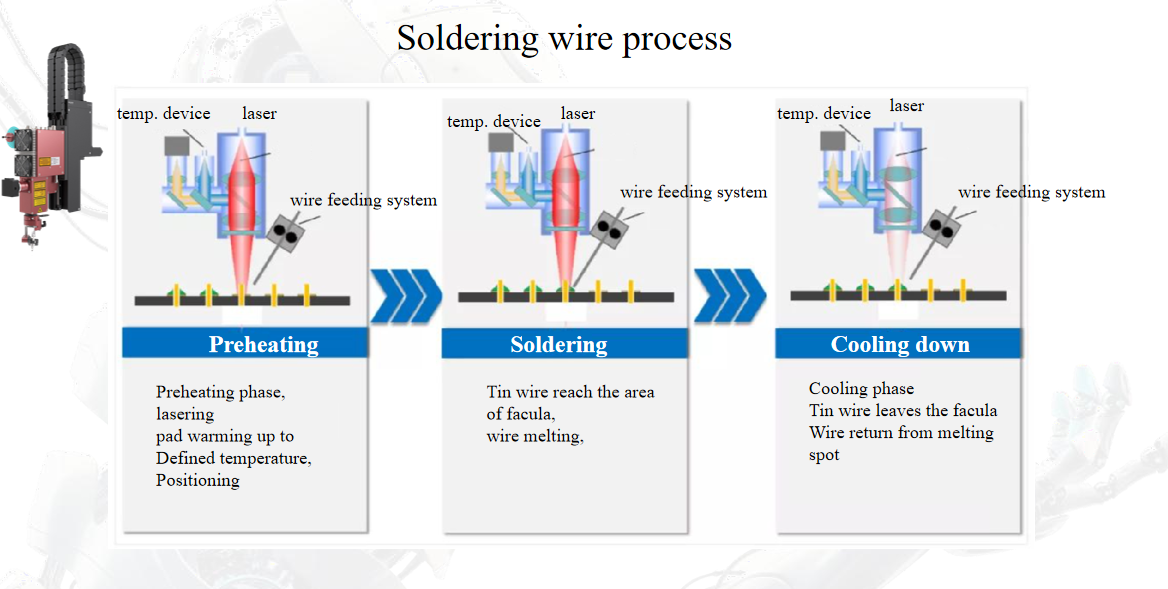
| Spatter and solder balls scattered around the joint | Ramp too fast, moisture or flux outgassing, wire fed too early | Add a 0.2–0.5 s pre-heat step at 30–40% power; delay wire feed until the pad reaches ~150 °C; dry-bake moisture-sensitive parts. |
| Burning or discolouration on the component body or flex | Peak temperature overshoot, wrong pyrometer emissivity, spot too large | Cross-check setpoint against a contact thermocouple; re-teach emissivity on the actual finish; reduce spot or add a mask. |
| Joint-to-joint variation within one batch | Fixture height drift, focus drift, pad thermal mass differences | Measure Z at three points on the fixture; re-focus; split the recipe into per-joint power groups rather than one average. |
| Bridging on fine pitch | Excess paste or wire volume, spot overlapping adjacent pads | Reduce deposit by 20–30%; shrink spot to ≤0.5 mm; check feed length calibration. |
| Brittle joints, field cracking after thermal cycling | Time above liquidus too long, thick intermetallic layer | Shorten dwell to keep time above 217 °C in the 1–3 s range for SAC305; re-check ramp rate. |
How do you qualify a batch on a portable laser soldering machine before releasing it?
Run a first-article of 5–10 units per part number and hold the batch until the checks below pass. These are the checks that catch process drift early:
- Visual: wetting angle under 90°, concave fillet, no icicles, no solder on component bodies — assess against IPC-A-610 Class 2 or 3 as your product requires.
- Cross-section on 2–3 joints: intermetallic layer typically 1–4 µm; voids under 25% of joint area for most automotive work.
- Strength: shear or pull test on a sacrificial sample; record the value and the failure mode (ductile through solder is preferred over interfacial separation).
- Thermal record: export the measured temperature curve for the first and last joint of the batch and compare peak and time-above-liquidus; a drift over 10 °C signals fixture or focus movement.
- Resistance: four-wire measurement on a sample joint; a rising trend across the batch indicates incomplete wetting or voiding.
- Repeatability check: re-load the same fixture five times and confirm alignment offset stays within your spot-tolerance budget (commonly ±0.05 mm for 0.4 mm pads).
FAQ
Can a portable laser soldering machine handle both prototype and small production runs?
Yes — that is its main use case. The same stored recipes serve the prototype build and the 200-piece run, provided the fixture is identical. The constraint is throughput: at roughly 1–5 s of beam time per joint plus load/unload, plan the machine for low joint counts per unit or for localised joints that a reflow oven cannot isolate.
Do I need nitrogen for lead-free laser soldering?
Not always, but it widens the process window. On ENIG with an active flux, air soldering is workable; on OSP, bare copper or heavily oxidised surfaces, 5–15 L/min of local N₂ at the nozzle measurably improves wetting and reduces spatter. If you see dull, non-wetting joints that respond to more power but then burn the part, try N₂ before you change the profile.
How many recipes can I store, and what belongs in one?
Most benchtop systems store 100+ programs. A complete recipe holds per-joint coordinates, spot size, laser power, dwell and ramp, feed length or ball size, N₂ flow, and the alignment offset for that fixture. Store the fixture ID with the recipe so an operator cannot load the wrong plate.
What power do I need for a connector with a large ground plane?
Size for the heaviest joint in your mix. A 0.4 mm signal pad may need 15–20 W for 1 s, while a connector shell tied to a ground plane can need 50–60 W or a longer dwell regardless of power. If your mix includes both, specify the higher power machine — headroom costs less than a second system.
What maintenance keeps a small-batch machine accurate?
Daily: clean the protective window and check N₂ flow. Weekly: verify focus height with a test coupon and confirm alignment offset. Monthly: recalibrate the pyrometer against a contact thermocouple and inspect feed rollers for wear. Log the results — drift is gradual, and the log is what tells you a joint problem is mechanical rather than a profile issue.
If you share your joint geometry, solder format and batch size, we can help you match a benchtop laser soldering configuration to your product mix.