



Machine vision does two distinct jobs in an automated laser soldering cell: it aligns the joint before the laser fires, and it inspects the finished fillet afterwards. A CCD camera with telecentric optics and controlled …
Machine vision does two distinct jobs in an automated laser soldering cell: it aligns the joint before the laser fires, and it inspects the finished fillet afterwards. A CCD camera with telecentric optics and controlled illumination locates the pad, solder ball or component to roughly ±10 µm, applies that offset to the galvo/laser program, then re-images the joint and grades fillet geometry, bridging, spatter and component shift against IPC-A-610 criteria — typically within the same 1–3 s cycle and without an extra handling step.
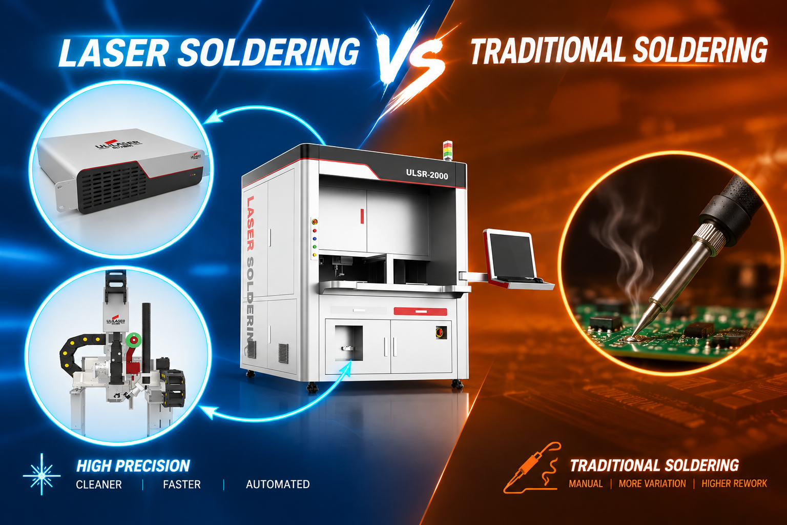
Where does machine vision sit in a laser soldering cell?
In practice the vision system appears at three points, and it helps to specify them separately because the optics, lighting and algorithms are different:
- Pre-solder alignment (vision-guided placement). The camera finds fiducials or the pad/lead pattern, computes X-Y-θ offset against the taught position, and corrects either the motion stage or the galvo scan field. This is what allows solder ball or wire feeding to land on a 0.2–0.4 mm pad without a mechanical fixture locating to better than 50 µm.
- Post-solder inspection (AOI). After the joint solidifies, a second image — or a second camera with a finer field of view — checks fillet presence, wetting, bridging, solder ball spatter, component offset and, where 3D is fitted, fillet height and wetting angle.
- In-process verification. Some cells verify ball presence and position, or confirm that the wire feed actually advanced, before energy is delivered. This is a cheap way to prevent “soldering into thin air” and scrap.
The alignment and inspection functions are usually split across two camera/lens combinations rather than shared, because alignment wants a 10–20 mm field of view and inspection of a fine-pitch joint wants 3–6 mm. Sharing one optic forces a compromise in pixel resolution that shows up later as false calls on fillet shape.
What camera resolution and lighting do you need to inspect solder fillets?
The selection rule that holds up on the floor: the smallest feature you must judge should be at least 3–5 pixels across, and solder fillet geometry needs the tighter end of that range because wetting angle is a slope measurement. Work backwards from the feature, not forwards from the megapixel count.
| Task | Field of view | Sensor (typical) | Pixel size on target | Reliable feature size |
|---|---|---|---|---|
| Fiducial / global alignment | 20 × 15 mm | 5 MP (2448 × 2048) | ~8 µm | ≥40 µm |
| Connector fillet AOI | 6 × 4.5 mm | 5 MP, telecentric | ~2.5 µm | ≥12 µm |
| Die / small component offset | 3 × 2.5 mm | 5 MP, telecentric | ~1.2 µm | ≥6 µm |
| Spatter screening | 10 × 8 mm | 5 MP | ~4 µm | ≥25 µm ball |
Lighting matters more than resolution once you pass 5 µm/pixel. Solder is specular and its surface finish changes with cooling rate and alloy, so a fixed exposure will saturate on one joint and underexpose the next. Configurations that work:
- Coaxial (axial) illumination for pad and fiducial contrast on flat surfaces.
- Segmented ring light, 4 or 8 quadrants, to reveal fillet slope — a concave fillet returns light differently by quadrant, which is how 2D systems infer wetting direction.
- Dome / diffuse light to suppress mirror flashes and keep the fillet silhouette stable.
- Blue (~470 nm) narrowband to cut sensitivity to ambient light and to the colour variation between flux residue and bare metal.
- Multi-exposure HDR (2–3 frames at 1–10 ms) combined into one image; reject any measurement where saturated pixels exceed about 5% of the joint area.
For height and wetting angle, add a laser triangulation profilometer or a phase-shift 3D head. Expect Z repeatability of about 0.5–1 µm on a good stage and wetting-angle repeatability in the ±3° range — enough to trend a process, not enough to replace a calibrated cross-section.
Which solder joint defects can vision catch — and which need X-ray?
Be honest with yourself about this split at the specification stage; it prevents an expensive expectation gap after acceptance.
| Defect | 2D vision | 3D vision | Note |
|---|---|---|---|
| Missing / insufficient solder | Yes | Yes (height) | Best indicator is fillet height vs. taught band |
| Excess solder, bridging | Yes | Yes | Bridges ≥25 µm detectable with adequate pixel size |
| Component offset / rotation / tombstone | Yes | Yes | Use telecentric lens to avoid parallax error |
| Solder ball spatter | Yes | Yes | Set a size threshold (e.g. 50 µm) per product |
| Wetting angle / concave fillet | Indirect | Yes | Slope measurement needs 3D or quadrant lighting |
| Internal voids, head-in-pillow | No | No | X-ray or cross-section; vision cannot see under the joint |
| Flux residue | Yes (UV/colour) | Limited | Requires a dedicated lighting channel |
How do you set acceptance criteria and prove the AOI is capable?
Translate the workmanship standard into numbers the tool can measure, then validate the tool against those numbers before you release it to production.
- Convert the standard once. IPC-A-610 Class 2/3 asks for a concave fillet, wetting angle ≤90°, continuous coverage and no bridging. Turn that into per-joint limits: minimum fillet height, maximum wetting angle, maximum offset, spatter count and size.
- Build a graded sample set. 30–50 joints spanning good, marginal and reject, graded independently by two experienced operators. This becomes your reference library and your regression test after any recipe change.
- Run a gauge study. For variable outputs such as fillet height, aim for %GRR under 10% (under 30% is the usual floor for conditional acceptance). For attribute calls, target kappa ≥0.75 across 3 operators × 3 trials.
- Verify the pixel scale, not just the image. Check against a certified target monthly and after any lens, camera or standoff change; a 0.2% scale error on a 6 mm field is 12 µm of hidden bias.
- Run a golden-board check at shift start. One known-good and one known-bad joint, pass/fail logged. It catches lighting drift and lens contamination in seconds.
- Log images by serial number. Storing the pre- and post-solder image pair against the unit ID is the fastest route to root cause when a field return appears.
Troubleshooting: why do vision systems produce false calls or miss defects?
Most complaints trace back to lighting, thresholding or calibration rather than the algorithm. The patterns repeat:
- False rejects on shiny, freshly cooled fillets. Cause: specular saturation clipping the fillet edge. Steps: enable HDR or reduce exposure until saturated pixels fall under 5%; add a dome diffuser; re-teach the edge threshold on three different joint finishes.
- Bridging escapes. Cause: pixel size too coarse or light angle flattening the meniscus. Steps: confirm ≥3 pixels across the expected bridge width; add low-angle side illumination; verify with a deliberately bridged sample.
- Drifting offset values through the shift. Cause: thermal growth in the camera mount or stage, or a loose standoff. Steps: re-run the calibration target at start and mid-shift; check repeatability on a fixed target 20 times — spread should stay under 1 pixel.
- Good joints called “insufficient solder”. Cause: limits copied from a different product’s recipe. Steps: rebuild limits from the graded sample set for that specific pad size and alloy.
- Overnight shift in contrast. Cause: flux aerosol on the window or lens. Steps: add a purge or protective window, and include a window-clean check in the shift routine.
FAQ
Can machine vision replace X-ray for solder void inspection?
No. Vision sees the outer surface of the joint; voids and head-in-pillow defects sit under the fillet or beneath the component. Use vision for fillet geometry, placement and surface defects, and keep X-ray or cross-section for internal voiding, sampling per lot or per critical part number.
Do I need 2D or 3D vision for laser soldering inspection?
2D is sufficient for presence/absence, offset, rotation, bridging and spatter, and it is faster and cheaper. Add 3D when you must measure fillet height, wetting angle or coplanarity against a numeric limit — which is common in automotive electronics where the joint is a safety-critical connection.
What false-call rate is realistic?
On a mature recipe with good lighting, joint-level false calls of roughly 1–3% are common in the first weeks and can be tuned below 1% with a graded sample set and a review station. Treat escape rate separately: the target there is zero on safety-critical joints, which is why the golden-board and calibration routines matter more than shaving the last point off false calls.
How often should the vision system be recalibrated?
Monthly against a certified target, plus after any lens, camera, standoff or lighting change, and after a thermal event such as a chiller failure or a move. Daily verification with a golden board in between.
Can one camera handle both alignment and inspection?
It can, but the field of view compromise usually costs more in false calls than a second camera costs to buy. Most inline laser soldering platforms we build use a wider-field alignment camera and a finer-field inspection camera, with the inspection head mounted after the solder point so imaging happens without an extra index.
If you share your pad sizes, alloy and target takt time, we can recommend a camera, lens and lighting configuration for your specific joints and run the numbers with you.