


Laser solder paste soldering uses a focused laser beam as the heat source to reflow a dispensed or stencil-printed solder paste deposit in a tightly defined area — typically a 0.3–2.0 mm spot, a 0.3–3.0 s heating cycle, …
Laser solder paste soldering uses a focused laser beam as the heat source to reflow a dispensed or stencil-printed solder paste deposit in a tightly defined area — typically a 0.3–2.0 mm spot, a 0.3–3.0 s heating cycle, and a heat-affected zone measured in millimetres rather than centimetres. It is the right process when the assembly cannot survive a full oven reflow, when only a handful of joints need paste reflow (connector tails, shield-can tabs, flex-to-PCB pads, sensor and terminal pins), or when adjacent parts are heat-sensitive. This guide gives the process windows, paste handling rules, defect troubleshooting and acceptance checks we use when commissioning laser solder paste soldering cells in production.
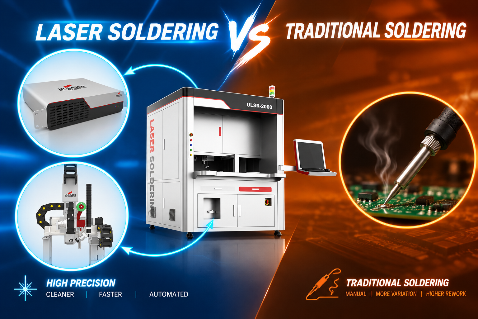
When is laser solder paste soldering the better choice than reflow or hot-bar?
Use laser reflow of solder paste when at least two of the following are true:
- Thermal budget is the constraint. Neighbouring parts are rated for short excursions only: MEMS sensors, electrolytic capacitors, optical modules, battery tabs, plastic connector bodies, or boards already populated with temperature-sensitive parts.
- Joint count is low but critical. One to roughly fifty joints per assembly — a subset reflow rather than a full board. Above that, oven or vapour-phase reflow is usually cheaper per joint.
- Topography blocks a stencil or hot-bar. Recessed cavities, tall components, stepped or flex substrates, or joints sitting next to 5 mm-tall parts that a thermode cannot reach.
- Substrate limits bulk heating. Thin flex, rigid-flex, ceramic hybrids, or heavy copper planes that would otherwise demand long oven dwell.
- Local rework is required. Removing and re-pasting a single device or connector tail without reflowing the whole assembly.
Where the situation is reversed — high joint count per board, uniform thermal mass, no heat-sensitive neighbours — a conventional reflow line will beat laser on cost per joint. Laser paste reflow is a precision tool, not a throughput tool.
How do you set the process window: power, spot, ramp and peak temperature?
Four variables matter: absorbed power density, spot-to-deposit ratio, ramp rate, and the peak/dwell pair. The laser spot should cover the paste deposit plus 0.2–0.4 mm of pad on each side; a spot smaller than the deposit concentrates energy at the centre and produces balling and burnt flux before the periphery has melted. Power density for near-infrared sources typically lands between 30 and 300 W/mm² of paste area, and the closed-loop controller — pyrometer or co-axial sensor, sampling at 1 kHz or better — should hold peak temperature within ±8–10 °C of setpoint with under 10 °C overshoot.
| Alloy | Liquidus (°C) | Peak target (°C) | Ramp (°C/s) | Dwell above liquidus (s) | Notes |
|---|---|---|---|---|---|
| SAC305 (Sn96.5Ag3Cu0.5) | 217–220 | 240–252 | 80–150 | 0.3–1.0 | Default for automotive and industrial joints |
| SAC0307 / low-Ag | 217–227 | 240–255 | 80–150 | 0.3–1.2 | Slightly wider window; better drop shock |
| Sn42Bi58 | 138 | 155–170 | 40–80 | 0.3–0.8 | Heat-sensitive parts; brittle — avoid high strain |
| Sn63Pb37 (legacy/exempt builds only) | 183 | 200–215 | 60–120 | 0.3–0.8 | Narrow plastic range; keep dwell short |
Two profile steps improve repeatability. A short preheat stage (80–110 °C for 0.2–0.5 s) volatilises solvent and lets the flux activate before the main pulse; a controlled cooldown of 30–60 °C/s avoids thermal-shock cracking in ceramic parts and reduces fillet shrinkage voids. Shielding gas — nitrogen at 5–20 L/min through a nozzle co-axial with the beam — keeps local oxygen below roughly 1000 ppm and measurably reduces balling and oxide films on slow-wetting pads.
How should solder paste be deposited and handled for laser reflow?
- Deposit geometry: 0.25–0.8 mm dots from a jet valve, or 0.10–0.20 mm printed height, with deposit volume repeatability within ±5% (CV). Paste volume inconsistency is the single most common cause of joint-to-joint variation in laser cells.
- Placement accuracy: deposit centred on the pad within ±50 µm; CCD vision alignment should reference pad geometry, not the part outline.
- Paste selection: fine powder (Type 4 or 5, 20–38 µm) jets more consistently and melts faster under a small spot; choose a flux system rated for fast ramp rates and confirm the paste’s recommended profile overlaps your laser window.
- Storage and warm-up: 2–8 °C storage, unopened warm-up of 1–2 h to room temperature before use, no re-refrigeration, and adherence to the supplier’s working life on the syringe (commonly 8–24 h). Cold paste condenses moisture and spatters.
- Stencil-plus-laser hybrid: for boards with many joints, print the whole board and laser-reflow only the heat-sensitive zone — this reduces the number of dispense operations dramatically.
What do common laser paste reflow defects look like, and how do you fix them?
| Symptom | Likely cause | Corrective action |
|---|---|---|
| Solder balling and spatter | Ramp too fast; moisture in paste; power spike at pulse start | Add 0.2–0.5 s preheat at 90 °C; warm paste fully; ramp the power setpoint instead of stepping it |
| Dull, grainy, cold joint | Peak below liquidus +20 °C; dwell too short; pyrometer mis-calibrated | Raise peak 10–15 °C, extend dwell 0.3 s, verify emissivity on a bare pad coupon |
| Tombstoning or part shift | Asymmetric deposit; spot offset from pad centre | Re-centre deposit, balance spot position, reduce ramp to 80 °C/s |
| Voids above 25% by X-ray | Flux outgassing, contaminated or oxidised pads, expired paste | Two-step profile, nitrogen shielding, IPA/plasma clean before dispensing, check paste date code |
| Charred or dark flux residue | Excess power density; spot smaller than deposit | Increase spot 0.2 mm, cut power 15–20%, shorten dwell |
| Pad cratering / delamination | Beam directly on laminate; no preheat | Defocus, add preheat stage, keep beam inside pad boundary |
| Incomplete wetting on heavy copper | Heat sinking through planes | Extend heating time 30–50%, higher-activity flux paste, preheat substrate to 60–80 °C |
What acceptance checks confirm a qualified joint?
- Visual: smooth, concave fillet with a wetting angle under 90° on pad and lead; no balling, no charred flux, no solder on solder mask.
- X-ray: void area typically ≤25% of joint area (tighter, 15%, for thermal or power joints) against the drawing or customer spec.
- Cross-section: intermetallic layer 1–3 µm; grain structure fine and uniform; no cracks at the pad interface.
- Mechanical: shear or pull test on first-article and periodic samples, with limits set from your own process capability study rather than a generic figure.
- Process monitoring: log the temperature curve of every joint; trend peak temperature and time-above-liquidus. A drift of more than 10 °C across a shift signals lens contamination, paste lot change, or pyrometer window fouling.
FAQ
Can I laser-reflow paste that was stencil printed rather than dispensed?
Yes, and it is often the fastest route: print the whole board, then laser-reflow only the zones that cannot take oven heat. Keep printed height uniform, because laser spot size and power are tuned to deposit thickness.
Which laser wavelength suits solder paste?
Near-infrared diode sources at 915/976 nm and fibre sources at 1070 nm cover most paste reflow work, because the flux vehicle absorbs and the metal absorption rises as it heats. Blue 450 nm sources help where very thin deposits sit on high-reflectivity copper and you need absorption from the first millisecond.
How fast is one joint?
Typical heating cycles run 0.3–3 s per joint, so a part with 10–30 joints takes a few seconds plus handling and vision time. The limiting factor in most cells is paste dispensing and part transfer, not the laser.
Will the beam damage parts next to the joint?
With a 0.5–1.5 mm spot and 1–3 mm working distance, the heat-affected zone stays within a few millimetres. Measure the neighbour’s body temperature on first articles; keep the rise below the component’s rated short-term excursion, and add a shield nozzle or a beam stop where clearance is under 1 mm.
Is nitrogen mandatory?
Not with a well-matched no-clean paste, but it widens the window: less balling, better spreading on oxidised pads, and more consistent fillet shape across paste lots.
Send us your board or package details, joint count, paste alloy and thermal limits, and we will help you size the laser source, spot optics and temperature profile for your application.