


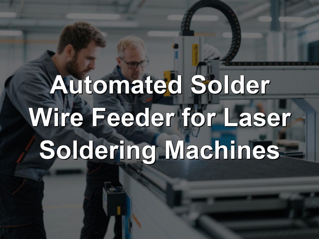
An automated solder wire feeder for laser soldering machines is a motorized module that pushes a measured length of solder wire — typically 0.3–1.2 mm diameter, solid or flux-cored — into the laser-heated joint zone at a…
An automated solder wire feeder for laser soldering machines is a motorized module that pushes a measured length of solder wire — typically 0.3–1.2 mm diameter, solid or flux-cored — into the laser-heated joint zone at a defined angle, speed and timing, then retracts slightly to break the wire from the molten pool. It converts a manual, operator-dependent step into a repeatable, program-controlled one: feed length per shot is usually programmable from 0.3 mm to 5 mm with ±0.05–0.1 mm repeatability, synchronized with the laser pulse and the CCD alignment offset. The feeder is the volume-dosing element of the process, so its accuracy and timing directly determine joint volume consistency, ball formation and wetting quality.
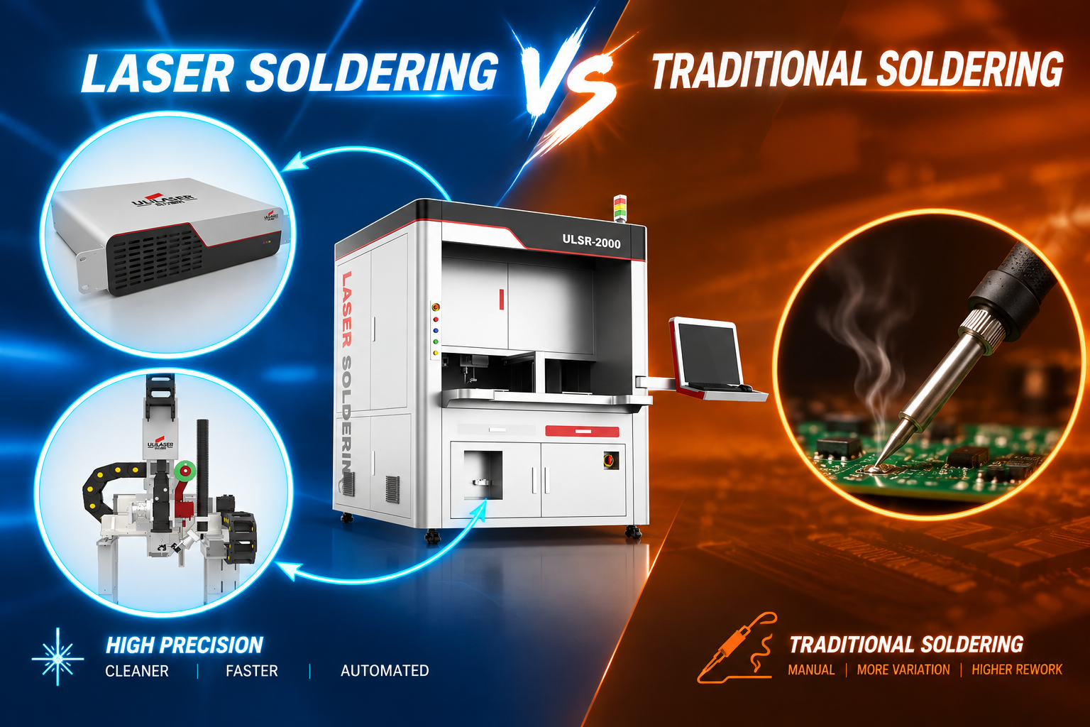
How does the wire feeder integrate with the laser soldering sequence?
In a laser soldering cell, the feeder is not simply “on” during heating. It runs a synchronized sequence, usually programmed as a set of time- or position-based steps in the machine controller:
- Alignment: the CCD camera locates the pad or lead, computes X/Y/θ offset, and the feeder nozzle plus laser spot are offset together so the wire always lands at the same point relative to the heated area.
- Preheat pulse: the laser raises the pad and lead to roughly 100–180 °C so the wire does not quench the surface on contact.
- Wire advance: the feeder pushes the set length (commonly 0.5–3 mm per joint) so the wire tip enters the laser spot at 0.3–1.0 mm from the beam centre.
- Main reflow pulse: closed-loop temperature control brings the joint to setpoint (typically 20–50 °C above the alloy liquidus, e.g. 230–260 °C for SAC305).
- Retract: the feeder reverses 0.1–0.5 mm to separate the wire from the pool before the alloy freezes.
- Dwell and inspection: a short cool dwell, then AOI checks volume, wetting angle and the absence of solder balls or spikes.
For connectors, coaxial cable terminations, wire-to-board joints and shielding-frame grounding, the same module is often run in “stitch” mode: multiple short feeds along a seam while the laser follows a path, rather than one large deposit.
Which feeder specifications actually matter for laser soldering?
Laser soldering is a small-spot, fast-ramp process, so the feeder needs finer resolution and better anti-slip behaviour than a typical iron-soldering feeder. The table below shows the ranges normally specified for production equipment.
| Parameter | Typical production range | Why it matters |
|---|---|---|
| Wire diameter | 0.3–1.2 mm (0.2–0.3 mm for fine pitch) | Sets the minimum achievable deposit and the guide-tube bore |
| Feed length per shot | 0.3–5 mm, programmable in 0.01 mm steps | Directly controls joint volume; must be small enough to avoid overshoot on 0402/0603 pads |
| Feed resolution / repeatability | ±0.05 mm best case, ±0.1 mm typical | Volume repeatability for small pads and fine-pitch connectors |
| Feed speed | 5–100 mm/s, ramped | Too fast causes wire buckling; too slow lets the pool freeze before the wire arrives |
| Retract (anti-drawback) length | 0.1–0.5 mm | Breaks the wire cleanly; prevents icicle/spike and wire sticking |
| Wire approach angle | 20°–60° from pad plane (30°–45° most common) | Shallow angles improve access on tall components; steep angles give more stable wire tip position |
| Wire tip to beam offset | 0.3–1.0 mm | Wire must sit inside the hot zone but not block the beam |
| Drive type | Stepper with dual knurled rollers; servo for ≤0.3 mm wire | Servo + encoder gives slip detection and closed-loop feed length check |
| Spool capacity | 100 g–1 kg | Small spools reduce wire memory and curvature; larger spools reduce changeover frequency |
| Wire-end / slip sensing | Encoder comparison or optical sensor | Stops the machine before a no-solder joint reaches the next station |
How do you set feed timing, angle and retract for a stable joint?
Three settings cause most of the difference between a stable process and a marginal one.
- Feed timing relative to the laser. Feed the wire after the pad reaches roughly 100–150 °C, not at the start of the pulse. Feeding into a cold pad quenches the surface, and the wire sticks and bends. Feeding too late leaves the wire sitting on top of an already-liquid pool, which produces a ball instead of a fillet.
- Approach angle and tip position. Set the angle so the wire tip contacts the pad-to-lead transition, not the pad centre. For fine-pitch connectors, use a steeper angle to keep the nozzle clear of adjacent pins, and confirm clearance with the CCD image before running production.
- Retract and cool-down. Retract must complete before the alloy passes its solidus. If the retract is too short, the freezing solder grips the wire and either pulls a spike or drags the wire out of the nozzle on the next move. If it is too long, the wire tip develops an oxidized ball that will not wet on the next shot.
Also match wire type to the feeder: flux-cored wire needs a slightly larger guide-tube clearance and more frequent cleaning, while solid wire requires separate flux dispensing and a tighter bore for positional accuracy. Store spools below roughly 30 °C and 60% RH; damp flux-cored wire causes spitting and porosity that looks like a laser problem but is not.
What causes wire feed defects, and how do you troubleshoot them?
| Symptom | Likely cause | Corrective action |
|---|---|---|
| Insufficient solder volume, joint starved | Roller slip, kink in guide tube, feed length programmed too short | Check encoder-vs-command feed length; replace worn rollers; straighten or replace tube |
| Spherical ball at wire tip, no wetting | Wire fed before pad is hot, or retract too long leaving an oxidized tip | Delay feed by 30–80 ms after preheat; reduce retract; add a short post-feed laser pulse |
| Wire sticks and bends on the pad | Pad too cold at contact, feed speed too high, angle too shallow | Raise preheat setpoint, ramp feed speed down to 20–40 mm/s, increase angle |
| Solder spike / icicle | Retract too short or too slow, laser off before retract completes | Increase retract to 0.2–0.3 mm and trigger it 20–50 ms before laser off |
| Wire jam at nozzle | Guide bore too tight, wire curvature from small spool, flux residue build-up | Increase bore clearance by 0.05–0.1 mm; use low-memory wire; add scheduled nozzle cleaning |
| Inconsistent volume shot to shot | Roller wear, spool drag, varying wire tension | Add a tension arm, log feed-length deviation, replace rollers on a fixed cycle |
| Porosity or spitting | Moisture in flux core, contaminated wire surface | Check storage conditions and wire lot; verify expiry and handling |
What acceptance checks confirm the feeder is production-ready?
- Feed-length repeatability: 30 consecutive feeds at production setting, measured with a micrometer or vision; the standard deviation should stay within one-third of the joint-volume tolerance.
- Pull or shear test: per the applicable IPC/J-STD criteria for the joint class, sampled at start-up, after feeder changeover and at a defined interval.
- Volume verification: X-ray or cross-section on the first-off and on any change of wire lot or diameter.
- Visual/AOI criteria: concave fillet, wetting angle within specification, no solder ball greater than the agreed limit, no spike, no residue bridging.
- Sequence audit: verify on the controller trace that feed, retract and laser pulses occur in the intended order and timing window after any program edit.
Run these checks after every wire-diameter change, guide-tube replacement or feeder service — these are the three events that most often shift deposited volume without any change to the laser program.
FAQ
Can one feeder handle both 0.5 mm and 0.8 mm wire?
Usually yes, but the guide tube and roller set must be changed to match the diameter. Running 0.5 mm wire through a 0.8 mm tube reduces positional accuracy and encourages buckling; keep a spare tube-and-roller kit per diameter and record the changeover.
Does the feeder work with flux-cored wire, or only solid wire?
Both are used. Flux-cored no-clean wire simplifies the process but leaves residue that builds up in the nozzle and needs scheduled cleaning. Solid wire gives cleaner joints in semiconductor and optical-module assemblies but requires a separate flux dispensing step.
How often should rollers and guide tubes be replaced?
Base it on fed wire length rather than calendar time — measure feed-length deviation and replace when it drifts beyond the acceptance band. In high-utilization automotive electronics lines, guide tubes are commonly treated as a scheduled consumable.
Why did joint volume drop after a wire spool change?
Check wire diameter with a micrometer first, then spool drag and wire curvature. A new spool with higher payoff resistance can cause intermittent roller slip that the encoder detects as a fault only at the extreme, while quietly shortening feeds in between.
Is the feeder compatible with inline automation?
Production modules normally provide SMEMA handshake, digital I/O and an Ethernet or RS-485 link to the line controller so feed programs are selected by product recipe and feeder faults stop the line before defective joints pass.
If you are specifying a wire-feeding laser soldering cell for an automotive electronics or semiconductor packaging application, share your wire diameter, joint geometry and cycle-time target and we can help match the feeder configuration to your process.