


Most fiber laser soldering problems fall into four buckets: the thermal profile is outside the process window, the solder feed is delivering the wrong amount at the wrong time, the optics or vision alignment have drifted…
Most fiber laser soldering problems fall into four buckets: the thermal profile is outside the process window, the solder feed is delivering the wrong amount at the wrong time, the optics or vision alignment have drifted, or contamination has changed how the joint absorbs heat. Because a focused 1070 nm beam heats in under a second, small drifts that would be invisible in a reflow oven show up immediately as cold joints, bridging, or spatter. The troubleshooting sequence below works from the joint outward — profile first, feed second, optics third — because roughly two-thirds of the faults we are asked to diagnose on inline fiber laser soldering systems turn out to be thermal or feeding related, not laser hardware failures.
Cold joints and incomplete wetting: where is the heat actually going?
A cold joint usually looks like a dull, grainy fillet with the solder balled up on the pad and no fillet rise onto the lead or terminal. Before touching laser power, measure what the joint actually reaches. Run a sacrificial board with a fine thermocouple bonded at the joint, or cross-check the closed-loop pyrometer against a contact reading, and confirm both peak temperature and time above liquidus (TAL).
| Alloy | Melting range | Target peak at joint | Time above liquidus | Typical use |
|---|---|---|---|---|
| SAC305 | 217–220 °C | 245–265 °C | 1–3 s | ECU, connector and sensor joints |
| SAC0307 | 217–228 °C | 245–270 °C | 1–3 s | Cost-sensitive lead-free assemblies |
| Sn63Pb37 | 183 °C | 205–225 °C | 0.8–2 s | Temperature-sensitive parts, legacy builds |
| Sn42Bi58 | 138 °C | 170–190 °C | 1–2 s | Optical modules, step soldering, thin substrates |
If measured peak temperature is on target but wetting still fails, the energy is arriving but leaving too fast. Thick copper ground planes, thermal vias, metal-backed boards and connector shells wick heat away faster than a 0.4 mm spot can replace it. Practical fixes, in order of cost: add bottom-side preheat (80–120 °C is common for lead-free), widen the spot or switch to a ring/dual-beam spot to heat the pad and lead simultaneously, extend dwell, then raise power. Remember that near-infrared absorptivity of tin-based solder is only roughly 15–30% and rises sharply once the alloy melts, so an oxidized or contaminated pad reflects more of the beam than a freshly plated one.
- Check flux: insufficient activity, or laser heat driving the flux off before the solder melts, produces the same symptom as low power.
- Check atmosphere: measure O₂ at the nozzle, not at the regulator. Lead-free joints generally need below 1000 ppm; oxidized reels and boards can defeat a good shield.
- Check surface finish: HASL, ENIG, OSP and bare copper need different profiles, and OSP has a limited number of heat cycles.
Solder ball, paste and wire feeding faults: why is solder missing the joint?
Feeding faults announce themselves as missing deposits, double deposits, or solder arriving after the beam has already ramped down.
- Ball feeding: choose a nozzle bore slightly smaller than the ball so the ball seats and is held by a small positive pressure (typically 0.1–0.3 MPa). Double feeds and jams usually trace to humidity in the ball reservoir (store in a dry cabinet), oxidized or tacky balls, worn feed tube bores, or static. A double feed lands two balls in one joint and shows up later as bridging.
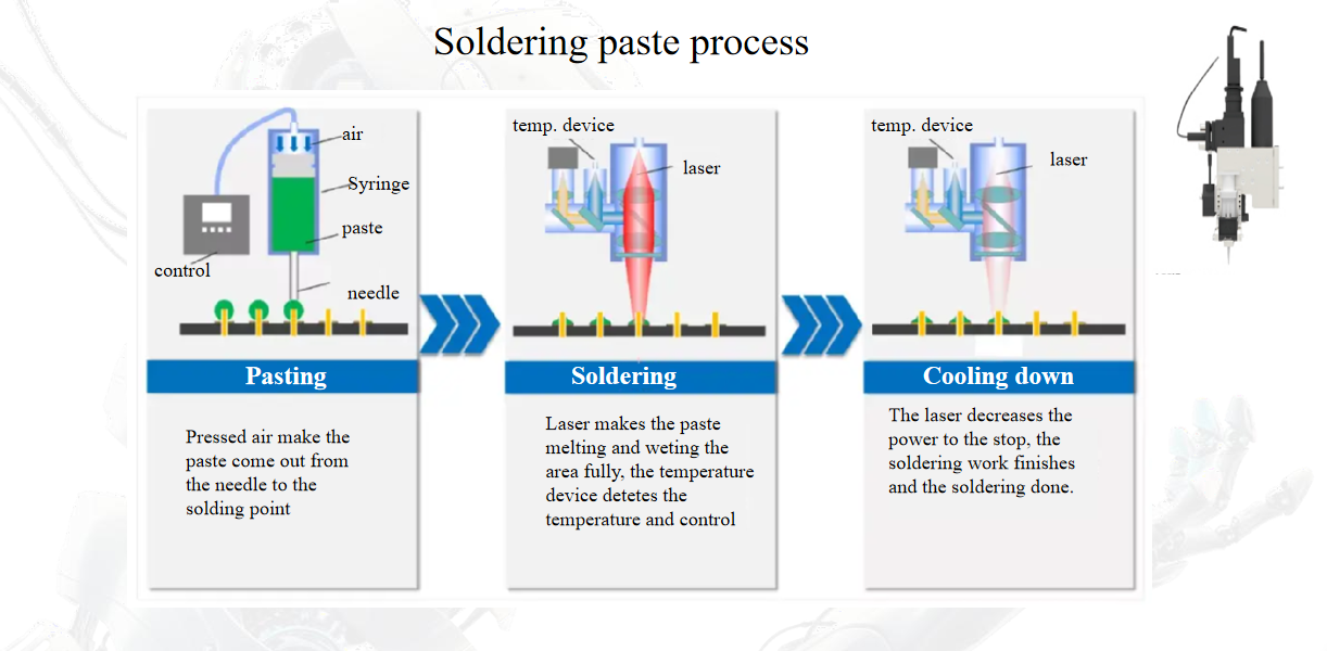
- Paste dispensing: verify dispensed volume by weight at the start of each shift and after any syringe change. Dry-out at the needle, incomplete thaw time, and expired paste change viscosity and cause both starved joints and slump. Needle-to-pad standoff matters as much as pressure.
- Wire feeding: the wire must reach the melt pool before the beam peaks and stop before the beam ends. A stub of unmelted wire or a detached ball indicates the feed-stop offset is late, the feed angle is wrong (30–45° to the pad works for most joints), or feed speed is mismatched to the ramp.
- CCD alignment: a camera-to-laser offset that drifts by even 50 µm moves the spot off the pad center. Re-teach fiducials and verify the offset with a burn-paper or test-coupon check at shift start, not just after a crash.
Bridging and spatter: which parameters are actually responsible?
Bridging between pads narrower than about 0.15 mm apart is a deposit-volume problem first and a laser problem second. Weigh or count the deposit, compare it to the pad and lead volume, and reduce it before adjusting optics. If volume is correct, check whether the spot is larger than the pad or offset toward the neighbor — both melt adjacent solder simultaneously.
Spatter rings and solder beads around the joint point to violent outgassing. Common causes: paste that absorbed moisture, flux with too much solvent, a ramp faster than the volatiles can escape, or nitrogen flow at the nozzle set high enough to blow molten solder (5–15 L/min is a workable range for most nozzles; direct the gas so it does not cross the melt pool). A two-step profile — a low-power preheat pulse followed by the main pulse — removes most spatter without lengthening cycle time noticeably.
Voids and porosity: how much is acceptable, and how do you reduce it?
Void acceptance is set by your customer’s drawing, not by the machine. Automotive programs commonly specify X-ray void limits of 20–25% of joint area, tightening to 10–15% for power devices and die-attach interfaces. Symptom to cause: voids concentrated at the interface usually mean oxide or contamination; scattered voids through the joint mean trapped volatiles.
- Bake moisture-sensitive boards per J-STD-033 before running; entrapped board moisture is a frequent and easily overlooked source.
- Slow the approach to liquidus so flux volatiles escape before the joint seals, then hold TAL within the window rather than shortening it.
- Confirm paste shelf life and thaw records, and verify flux coverage is uniform — patchy flux creates patchy voids.
- Re-check nitrogen purity and nozzle position after any fixture change; a shifted nozzle can halve effective shielding on one side of the joint.
Drift across a production shift: pyrometer, window contamination and focus
The most common failure pattern we see is a slow, self-inflicted power creep: flux aerosol deposits on the protective window, transmission drops, joints go cold, an operator raises power to compensate, the window is then cleaned, and the next boards are over-powered. Clean the protective window on a fixed interval (every 4–8 hours is typical in high-flux operation) and verify transmission with a power meter weekly. Similarly, calibrate the closed-loop pyrometer against a contact thermocouple on a monthly schedule and check emissivity settings whenever the board finish or solder alloy changes.
| Symptom | Most likely cause | First check |
|---|---|---|
| Dull, grainy fillet; solder balls up on pad | Energy below window or heat sinking | Peak temperature and TAL on a sacrificial board; preheat |
| Wets pad but not lead or terminal | Lead oxidation or insufficient flux | Flux weight per joint; lead finish and date code; O₂ at nozzle |
| Two balls in one joint | Feeder double-feed | Reservoir humidity, tube wear, hold pressure |
| Unmelted wire stub | Feed and laser timing out of sync | Feed-stop offset, wire angle, feed speed |
| Bridging on fine-pitch pads | Excess deposit or spot offset | Dispense weight; camera-to-laser offset; spot diameter |
| Charred flux residue | Peak temperature too high or window contaminated | Profile log; window transmission; power setting history |
FAQ
Can a fiber laser solder through-hole and connector pins?
Yes. Through-hole and pin-in-paste joints are routine, provided the barrel is preheated enough that solder wicks before the surface solidifies. Add bottom-side preheat and extend TAL slightly on thick boards.
What spot size should I use for small SMT pads?
A spot roughly matched to the pad, typically 0.3–0.8 mm for 0402 and fine-pitch work, keeps the beam off neighboring deposits. Larger spots heat faster but cost you selectivity.
Is nitrogen mandatory?
For lead-free alloys it is effectively necessary to hold O₂ below about 1000 ppm at the joint. For tin-lead work with active flux, air soldering can be acceptable on clean pads.
Why do joints pass on the test coupon but fail in production?
Almost always a change in thermal mass or fixturing — ground planes, connector shells, board thickness, or a fixture that shadows the shield gas. Re-run the profile on real production boards, not coupons.
How often should the pyrometer be recalibrated?
Monthly against a contact thermocouple is a practical baseline, plus any time the alloy, board finish, or spot size changes, because all three shift the emissivity and measurement field.
If you send us your joint cross-section, alloy, pad geometry and current profile, our application engineers can help you narrow down which of these variables is limiting your yield.