


Laser soldering in medical device manufacturing is a non-contact reflow process in which a focused diode-laser spot (typically 915 nm or 980 nm, delivered through fiber optics) heats one joint at a time — solder paste, a…
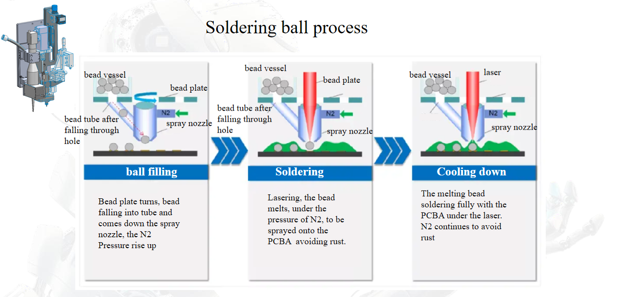
Laser soldering in medical device manufacturing is a non-contact reflow process in which a focused diode-laser spot (typically 915 nm or 980 nm, delivered through fiber optics) heats one joint at a time — solder paste, a solder ball, or solder wire — while closed-loop pyrometer feedback holds the profile within a few degrees of setpoint. Because no iron tip touches the part, fine-pitch connectors, sensor leadwire terminations, catheter electrodes and implant feedthroughs can be joined with a heat-affected zone of a few hundred microns, and every joint can be logged as a temperature curve for traceability.
Why Use Laser Soldering Instead of an Iron or Hot-Bar on Medical Assemblies?
The drivers are usually mechanical and documentary rather than speed alone:
- No contact, no contamination. An iron tip is a consumable that oxidizes, picks up flux char and must be dressed; laser energy arrives through air or a shielding-gas nozzle, so there is no tip-to-part wear and no tool-transfer of residue onto a joint that may sit near a patient-contacting surface.
- Localized heat input. A 0.3–0.8 mm spot concentrates energy at the joint. Neighbouring MEMS sensors, polymer catheter shafts, heat-shrink strain reliefs and battery separators stay well below their glass-transition or softening limits when the spot and dwell are set correctly.
- Repeatable, digitized profiles. Power, ramp rate, dwell and peak temperature are recipe parameters, not operator feel. The same recipe runs on every unit, and the measured curve can be stored per serial number.
- Access to constrained geometry. Leadwires entering a connector from three sides, or a joint recessed behind a shield, are reachable with a 90°-angled nozzle or a small spot where an iron body simply will not fit.
Which Medical Device Joints Suit Laser Soldering — and Which Don’t?
Laser soldering wins where the joint is small, the thermal mass is low and the surrounding materials are delicate. It is a poor choice for through-hole pins on thick power boards, large ground planes, or joints that need more than roughly 2–3 s of energy — the laser cannot compete with a wave or selective-solder bath there on throughput.
| Joint type | Typical feature size | Solder feed | Process note |
|---|---|---|---|
| FPC-to-PCB fine-pitch connector | 0.3–0.5 mm pitch | Type 4 paste or 0.25–0.4 mm wire | Spot 0.4–0.6 mm; nitrogen below 1000 ppm O₂ |
| Sensor leadwire termination | 0.1–0.3 mm wire | 0.2–0.3 mm wire | Clamp the wire so it does not shadow the beam |
| Catheter / guidewire electrode | 0.15–0.4 mm ring | Micro-ball 0.15–0.3 mm | Limit total energy; check polymer shaft temperature |
| Implant feedthrough / hermetic package | 0.3–1.0 mm pad | AuSn preform | Fluxless in nitrogen; peak 300–325 °C |
| Micro-coil / magnet wire | 0.05–0.15 mm wire | Wire or paste | Short dwell; verify no insulation charring |
What Process Parameters Should You Lock Down?
Six parameters define the window; change one and the others usually need re-checking:
- Peak power and spot diameter. Micro solder joints generally run 3–30 W into a 0.2–1.5 mm spot. Irradiance, not raw power, is the number to compare between machines.
- Ramp rate. 50–150 °C/s is typical. Faster ramps cut cycle time but drive flux outgassing hard and cause spatter and voids.
- Dwell above liquidus. Usually 0.3–2.0 s. Long dwells grow intermetallic thickness and char flux without improving wetting.
- Feedback loop. Pyrometer sampling at 1–10 ms with the spot coaxial to the beam. Emissivity differences between gold pad, solder and bare FR-4 are the main source of temperature error — calibrate per board finish.
- Atmosphere. Below 1000 ppm O₂ for general work; below 50 ppm for fine-pitch and fluxless AuSn.
- Solder alloy. The profile follows the alloy, not the other way round.
| Alloy | Solidus/liquidus | Peak joint temperature | Dwell above liquidus | Use case |
|---|---|---|---|---|
| Sn63Pb37 | 183 °C | 200–215 °C | 0.3–1.0 s | Legacy medical boards under RoHS exemption |
| SAC305 | 217–220 °C | 235–250 °C | 0.4–1.5 s | General medical PCB assembly |
| SnBi low-temperature | 138 °C | 155–170 °C | 0.3–0.8 s | Temperature-sensitive flex and sensor modules |
| AuSn 80/20 | 280 °C | 300–325 °C | 0.5–2.0 s | Hermetic implant packages, fluxless |
How Do You Validate and Monitor the Process for ISO 13485 and FDA Review?
Treat the laser as a special process and validate it the way you would any other:
- IQ: record laser power at the workpiece with an external meter, verify focus distance and spot size, verify gas flow and O₂ ppm, verify pyrometer calibration against a contact thermocouple on a sacrificial coupon.
- OQ: challenge the edges — power ±10%, dwell ±20%, focus ±0.1 mm — and show the joint still meets the internal visual and strength spec across the whole window.
- PQ: three consecutive lots, with pull or shear strength recorded per joint and Cpk ≥ 1.33 on the strength distribution; voiding by cross-section typically ≤ 10% of joint area for implantable and ≤ 25% for external devices.
- Ongoing: highly inline AOI after reflow, plus per-serial temperature-curve logging with an audit trail that satisfies 21 CFR Part 11. Acceptance criteria normally reference IPC-A-610 Class 3 and J-STD-001, with an added internal standard for residue (ionic contamination below 1.56 µg/cm² NaCl equivalent) and ISO 10993-1 review wherever residue could contact tissue.
What Do Common Defects Look Like, and How Do You Troubleshoot Them?
| Symptom | Likely cause | Corrective action |
|---|---|---|
| Dull, cold-looking joint; incomplete fillet | Pyrometer reading low due to pad emissivity, or energy absorbed by a shiny leadframe | Recalibrate against a thermocouple coupon; raise peak setpoint 10–15 °C; extend dwell 20% |
| Solder balls and spatter around the joint | Ramp too steep, flux outgassing explosively; paste with absorbed moisture | Halve the ramp rate; add 1–2 s preheat step; check paste storage and thaw log |
| Voids visible in X-ray or cross-section | Flux entrapment, oxidized pad finish, insufficient nitrogen | Slow the ramp through the flux activation range; verify O₂ ppm at the nozzle; review pad finish shelf life |
| Brown or charred residue | Peak temperature too high or dwell too long | Reduce peak 10 °C, shorten dwell, or switch to a no-clean flux rated for the profile |
| Joint-to-joint variation on the same panel | Focus drift from board warpage, or inconsistent part seating | Add Z-height mapping or a spring-loaded nozzle standoff; check fixture flatness |
| Discoloured or deformed polymer nearby | Spot too large, or reflective nozzle scattering energy | Reduce spot 20–30%, add a shield or masking, re-measure shaft temperature with an IR camera |
FAQ
Can laser soldering replace the iron for every joint on a medical PCB? No. It is the better tool for fine-pitch, low-thermal-mass and heat-sensitive joints; through-hole pins on heavy ground planes, large shields and mixed-technology boards usually still need selective solder or a iron/hot-bar step. Most lines run laser for the critical joints and conventional methods elsewhere.
Will the laser damage MEMS sensors or polymer catheter components nearby? The heat-affected zone is typically a few hundred microns when the spot is kept at 0.3–0.6 mm, but it must be verified, not assumed. Run an IR camera or thermocouple check on the nearest sensitive feature at the worst-case profile and keep a documented margin below its rated limit.
Do you still need flux? Yes for paste and cored wire on standard PCB finishes; the laser only replaces the heat source, not the oxide removal. Fluxless AuSn on hermetic feedthroughs is the exception, and it requires oxygen below 50 ppm plus tight profile control.
How do you prove a joint actually reached reflow temperature without touching it? Two ways: pyrometer calibration against a contact thermocouple on a representative coupon, and destructive verification by cross-section showing a proper intermetallic layer. Both belong in the OQ package, and the pyrometer should be re-verified on a defined interval.
What cycle time should we expect? Single-joint laser reflow is usually 0.5–3 s of beam-on time; with CCD alignment and indexing, 1–3 joints per second is realistic on a small assembly. Throughput depends far more on part handling and alignment than on the laser itself.
If you are selecting a laser soldering platform for a medical build, send us your joint geometry, alloy and stack-up and we will help you define the process window and the validation evidence you will need.