


Laser soldering wins when the joint is small, dense, heat-sensitive, or surrounded by parts that cannot take a second reflow; traditional soldering — iron, hot air, wave and reflow — wins when the joint has large thermal…
Laser soldering wins when the joint is small, dense, heat-sensitive, or surrounded by parts that cannot take a second reflow; traditional soldering — iron, hot air, wave and reflow — wins when the joint has large thermal mass, when volumes are high, or when cost per joint dominates. Neither is universally “better”: the right answer depends on pad geometry, board thermal mass, alloy, housing material and how much temperature the part can survive. The comparison below gives you the measurable criteria to make that call on your own assembly.
Laser Soldering vs Traditional Soldering: How Do the Heat Sources Actually Differ?
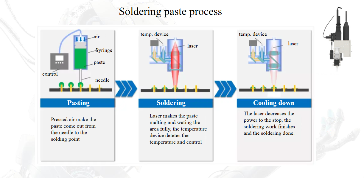
The difference is not just “new versus old” — it is a different energy transfer mechanism. A laser delivers photon energy that is absorbed at the joint surface and converted to heat within milliseconds, with no contact and no need to bring the whole board up to temperature. Traditional methods conduct heat through a tip, convect it through hot gas, or heat the entire board in an oven.
This matters in three practical ways. First, the heated volume is limited to a spot of roughly 0.3–3 mm, so an adjacent 0.4 mm-pitch connector body or an already-mounted image sensor sees only a short, small temperature rise. Second, ramp rates of 100–300 °C/s are achievable, which shortens time-above-liquidus and limits intermetallic growth. Third, because there is no contact force, there is no tip-induced pad damage and no solder wicking onto a tip. The trade-off is that laser absorption depends on surface finish and geometry — bare copper, ENIG, HASL and gold-plated pads absorb differently — which is why closed-loop pyrometer control and, for some joints, a low preheat or dual-wavelength setup are used.
Note that this comparison covers soldering only, where a filler alloy melts below roughly 450 °C. Laser welding, which fuses base metal, is a separate process with different equipment and is not part of this discussion.
| Criterion | Laser soldering | Soldering iron (contact) | Hot air / convection | Reflow oven |
|---|---|---|---|---|
| Heat transfer | Photon absorption at the joint, non-contact | Conduction through the tip | Forced hot-gas convection | Whole-board convection / IR |
| Heated area | 0.3–3 mm spot, joint only | Tip footprint 0.5–5 mm | 3–10 mm nozzle zone with spill | Entire board |
| Typical ramp rate | 100–300 °C/s | 20–60 °C/s | 10–40 °C/s | 1–3 °C/s (profile-limited) |
| Temperature feedback | Pyrometer / two-colour, closed loop ±5–10 °C | Tip thermocouple; joint temperature indirect | Gas temperature at nozzle | Profile plus board thermocouples |
| Contact force on joint | None | 1–5 N typical | None | None |
| Heat seen by neighbours | Minimal | Moderate | Noticeable, nozzle-dependent | Full board thermal cycle |
| Consumables | Cover glass, nozzle, wire or ball, nitrogen | Tips, flux, wick | Nozzles, filters | Nitrogen, filters, belt wear |
| Typical best fit | Fine-pitch, heat-sensitive, localized and high-mix joints | Rework, low volume, through-hole touch-up | Local rework, heat-shrink, preheat | High-volume SMT panels |
Which Joints Genuinely Benefit from Laser Soldering?
In production the laser earns its place where the joint is constrained rather than where it is simply small:
- Fine-pitch connectors. 0.3–0.5 mm pitch board-to-board and FPC connectors where a 0.5 mm iron tip bridges two leads and a hot-air nozzle cannot reach without shadowing.
- Heat-sensitive neighbours. Camera modules, MEMS sensors, LEDs and plastic connector housings that deform or shift during a second reflow pass.
- Shielded and recessed joints. RF shield frames, metal cans and deep cavities where convection is blocked by geometry.
- Wire-to-pad and flex-to-PCB. Automotive sensor tails and harness pads, soldered with wire feed or preform without clamping force.
- Solder ball jetting. 0.15–0.76 mm balls jetted onto pad arrays for package-level and connector applications, with the ball volume set by nozzle diameter rather than by paste print quality.
- Localized rework on assembled boards. Adding or repairing one joint beside parts that cannot be reflowed again.
A typical process window for SAC305 with a diode or fibre source looks like this:
| Parameter | Typical range | Selection note |
|---|---|---|
| Laser source | Diode 915/976 nm; fibre 1070 nm | Diode suits cost-sensitive spots; fibre gives tighter beam for sub-0.5 mm joints |
| Power at work surface | 30–150 W | Set by spot size and joint mass, not by board size |
| Spot diameter | 0.3–3 mm | Match the pad/lead, not the whole component |
| Peak joint temperature | 220–245 °C (SAC305); 190–210 °C (Sn63Pb37) | 25–40 °C above liquidus for reliable wetting |
| Time above liquidus | 0.3–2 s | Long enough to wet, short enough to protect the housing |
| Wire diameter / feed | 0.3–0.8 mm at 5–30 mm/s | Feed profile ramped with the temperature curve |
| Nitrogen | 5–15 L/min, O₂ below 1000 ppm | Improves lead-free wetting on ENIG and copper |
| Vision alignment | CCD ±10–25 µm | Required for pitch below 0.5 mm and transparent parts |
When Should You Stay with Traditional Soldering?
Laser is a poor fit for joints whose thermal mass exceeds what a 0.3–3 mm spot can bring to temperature in a couple of seconds. Practical cases where an iron, wave or reflow remains the better choice:
- Large thermal mass. Through-hole pins above about 1 mm diameter, thick ground planes and metal-backed boards sink heat faster than the spot delivers it; you get cold joints or long cycles.
- High-volume simple boards. A single reflow or wave pass solders hundreds of joints at once; per-joint laser time of 0.3–2 s only pays off when the joint count is low or the joints are unreachable.
- Mixed assemblies already in reflow. If the whole board is going through the oven anyway, adding laser stations only makes sense for the few joints the oven cannot serve.
- Low-volume rework. An iron with a good tip is still the cost-effective, fastest way to fix one joint.
In practice, most automotive electronics and semiconductor packaging lines use both: reflow for the mainstream SMT, laser for the connector, shield, sensor and wire joints that reflow cannot reach without damaging something.
What Failures Look Like and How to Troubleshoot Them
| Symptom | Likely cause | First corrective action |
|---|---|---|
| Cold joint, dull or grainy fillet | Energy below setpoint, drifted power, low absorptivity on bare copper | Verify actual power with an external meter; check pyrometer emissivity calibration; add preheat or raise peak temperature 10 °C |
| Ball not fully reflowed / solder sitting as a lump | Insufficient time above liquidus, ball diameter mis-set, contaminated pad | Extend dwell in 100 ms steps; confirm nozzle-to-ball match; check pad cleanliness and flux activity |
| Burned or lifted pad, discoloured flex | Over-power, spot larger than the pad, missed alignment | Reduce power 10–20 %, shrink spot, re-run CCD alignment; verify the spot is not clipping the cover layer |
| Excess voiding (over 25 % by X-ray) | Oxidation, poor nitrogen coverage, contaminated alloy | Check O₂ reading at the nozzle, increase flow, verify wire/ball shelf life and storage |
| Iron: cold joint on a ground pad | Tip cannot overcome thermal mass | Increase tip size and setpoint, add board preheat, or move the joint to a laser/convection station |
| Hot air: bridging or tombstoning | Uneven nozzle flow, shadowing, excessive paste | Balance nozzle, reduce paste volume, adjust placement pressure |
Acceptance Checks Before You Commit to Either Process
- Visual and cross-section: concave fillet with a wetting angle under 30°, no cracks, no Icicle; cross-section for intermetallic thickness in the 1–3 µm range — thicker indicates excessive time above liquidus.
- X-ray: voiding under 25 % of joint area for most automotive and package specifications; check the actual drawing limit.
- Mechanical: pull or shear test on witness samples; compare against the drawing minimum, and repeat after thermal cycling (−40 to +125 °C, 500–1000 cycles) to catch IMC-driven embrittlement.
- Process capability: run 30 consecutive joints and record peak temperature and time above liquidus; a spread wider than ±10 °C at the joint means the energy delivery or the absorption path needs attention.
FAQ
Is laser soldering faster than iron soldering?
Per joint, yes in most cases: a laser spot reaches soldering temperature in 0.2–1 s, while an iron takes several seconds to recover after each contact. But the laser is not automatically faster per board — if a reflow oven solders 400 joints in one pass, no serial process competes with that. Compare cycle time per board, not per joint.
Can laser soldering replace a reflow oven?
Only for a minority of joints. Reflow remains the most efficient way to attach high-count SMT arrays. Laser is used for the joints reflow cannot serve: heat-sensitive parts, shielded cavities, connectors added after reflow, and localized rework.
Does laser soldering work for through-hole connectors?
It can, but thermal mass is the limit. Pins up to about 0.8–1 mm with a moderate barrel can be soldered with wire feed and a 1–2 mm spot, sometimes with bottom-side preheat. Above that, wave or selective soldering is usually more stable.
What drives the cost comparison?
Look at cost per acceptable joint, not equipment price. Traditional lines carry tips, nozzles, filters and nitrogen; laser lines carry cover glass, nozzle wear and calibration time, plus a higher capital cost. Laser becomes economical when it removes a second reflow pass, eliminates a rework station, or enables a joint that would otherwise be hand-soldered with variable quality.
If you send us your pad geometry, alloy, housing material and cycle-time target, our application engineers can run a joint-level comparison and recommend a process window for your assembly.