


A laser soldering station vs an inline system comes down to volume, mix and who owns the process: buy a station when you are proving the process, running high-mix low-volume or doing rework, and specify an inline system …
A laser soldering station vs an inline system comes down to volume, mix and who owns the process: buy a station when you are proving the process, running high-mix low-volume or doing rework, and specify an inline system once a stable product family carries roughly 15,000–20,000 joints per production day or more. Both use the same core physics — a 10–50 W fiber-coupled or diode laser, focused spot, closed-loop pyrometer or thermal-camera feedback and solder ball / paste / wire feeding — so the laser source is rarely the deciding factor. What separates them is material handling, alignment repeatability, changeover time and traceability.
What actually differs between a laser soldering station and an inline laser soldering system?
Strip away the enclosure and the two machines share a great deal: laser source, beam delivery, focus optics, closed-loop temperature control, solder feeding and often the same post-solder inspection camera. The differences sit in the motion and handling layer.
- Alignment: a station relies on an operator or a simple fixture; expect ±0.1–0.2 mm placement, which is fine down to about 0.4 mm pad pitch. An inline cell uses CCD fiducial recognition with ±10–25 µm repeatability, which is what makes 0.25–0.3 mm pitch and 0201-class components achievable.
- Handling: stations are load-by-hand, one board or one connector at a time. Inline systems index carriers on an SMEMA-compatible conveyor with a fixed stop station, so the board position is identical for every cycle.
- Data: stations typically log locally, if at all. Inline cells push per-joint temperature curves, peak temperature, ramp rate and alignment offsets to MES/SPC, which is what automotive ECU and sensor customers usually require for PPAP.
- Changeover: a recipe change on a station is a fixture swap plus a few parameters — 5–15 minutes. On an inline cell it is a program recall plus carrier change, typically 10–30 minutes, but it only works if the carrier family is designed for it.
When is a benchtop laser soldering station the right buy?
A station earns its place in five situations:
- New product introduction. You need to establish the process window — peak temperature, ramp rate, nitrogen flow, solder ball diameter — before committing capital to automation.
- High-mix, low-volume. Fewer than roughly 200–400 boards per day with frequent model changes. Fixture cost per model is low; conveyor and carrier cost is not.
- Connector and single-point work. Wire-to-board terminals, shielded connectors and heat-sensitive assemblies where only one or two joints per board need laser heat rather than a full reflow pass.
- Rework and second-op repair. Selective removal and re-soldering of a single joint without disturbing neighbouring parts or the whole assembly’s thermal history.
- Capacity overflow. A station next to the line absorbs spikes without stopping the main conveyor.
The trade-off is labour dependency. Realistic throughput for one operator with a manual fixture is 250–400 joints per hour including load, align, solder and unload. Yield also drifts with operator fatigue; plan on a first-pass yield about 1–3 percentage points below an equivalent inline process unless you add a vision alignment option.
When does an inline system pay for itself?
Run the arithmetic before you run the brochure. Take annual joint count, divide by available production seconds, and compare against the cell’s realistic cycle time — not its best-case number.
Worked example: 400 boards per day × 24 laser joints = 9,600 joints/day. Over an 8-hour shift at 80% OEE that is 28,800 available seconds, so the cell must average 3.0 seconds per joint to keep up on one shift. A galvo-based inline cell with 0.5–1.2 s beam positioning per joint plus 6–10 s conveyor index comfortably meets that; a station needing 8–10 s of manual handling per board does not, and would need three shifts or two machines.
Specify inline when most of these are true:
- Stable product family with a joint count above ~15,000 per day, or a clear 12–18 month forecast to that level.
- Floor space for 3–8 m of line plus fume extraction and nitrogen supply.
- Pitch below 0.4 mm, or a customer requiring per-joint traceability.
- Changeover frequency of once or twice per shift, not once per hour.
- Someone on staff who can own recipes, calibration and preventive maintenance.
Side-by-side comparison: laser soldering station vs inline system
| Parameter | Benchtop laser soldering station | Inline laser soldering system |
|---|---|---|
| Laser source | 10–50 W fiber-coupled / diode, 915–980 nm typical | 20–50 W, same family, often with beam splitter or galvo |
| Spot diameter | 0.3–2.0 mm, manual focus adjust | 0.2–1.5 mm, programmable focus and beam shaping |
| Alignment | Operator / fixture, ±0.1–0.2 mm | CCD fiducial, ±10–25 µm |
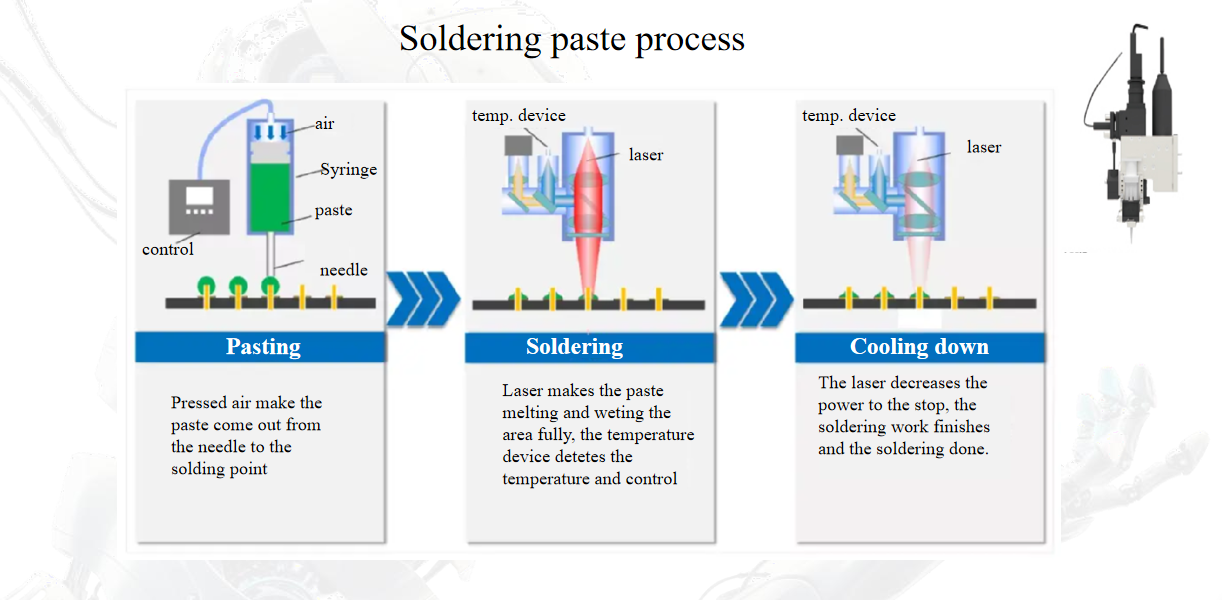
| Solder feed | Wire 0.3–0.8 mm, paste syringe, or single ball | Ball jetting, paste jetting or wire, automatic replenishment |
| Temperature control | Pyrometer closed loop, 1–10 ms sampling | Pyrometer or thermal camera, per-joint curve logged |
| Typical throughput | 250–400 joints/hour with operator | 1,200–3,000 joints/hour, up to 400–600 boards/shift |
| Footprint | 0.6–1.5 m² bench space | 3–8 m line length plus services |
| Changeover | 5–15 min, fixture swap | 10–30 min, program recall + carrier |
| Traceability | Local log, manual export | MES/SPC, per-joint data, barcode-linked |
| Relative capital cost | Baseline | Roughly 4–8× the station, plus carriers and services |
| Best fit | NPI, high mix, rework, connectors | Stable volume, fine pitch, automotive/semi packaging |
Which failure symptoms should you expect — and how do you troubleshoot them differently?
Both platforms share a failure catalogue, but the root causes diverge because of what varies between cycles.
- Cold joint or incomplete wetting. On a station, check focus distance first — an operator-adjusted head is the most common drift source — then verify nitrogen flow (target <1,000 ppm O₂ at the nozzle) and pad oxidation. On an inline cell, check pyrometer calibration and emissivity settings against a thermocouple-verified profile; a 20–30 °C measurement offset is enough to under-fire every joint on the carrier.
- Misplaced solder ball. Station: nozzle contamination or feeder slip. Inline: ball jetting nozzle wear, and carrier seating that shifts the board 50–100 µm between indexes.
- Sporadic thermal damage. Station: operator increases power to compensate for a dull focus. Inline: recipe applied to a board with different copper balance or ground plane — thin and thick copper need separate recipes even within one part number family.
- Voids above 25% of joint area. Usually flux outgassing from too fast a ramp; slow the first 100 ms of the pulse and check paste or ball storage and expiry.
- Inline-only symptom — shift drift. First-pass yield is good at 08:00 and falls by 14:00. Log the peak-temperature curve hourly; thermal drift in the optics enclosure or a sagging conveyor height are the usual culprits.
What should the acceptance test include before you sign?
- Station: 30 consecutive joints on the same pad, measure positional scatter and peak-temperature spread (target ±5 °C); pull-test 10 joints to your internal spec; time a realistic board from load to unload with the actual operator.
- Inline: a 30-board run with Cpk calculated on joint height and peak temperature (target ≥1.33); a changeover timed by your own technician; false-call rate of the CCD alignment and post-solder AOI over 200 joints; documented uptime expectation and spare-parts list for nozzles, feeders and pyrometer windows.
- Both: agree on the inspection standard up front — IPC-A-610 / J-STD-001 class, plus a voiding criterion — and verify the machine can hold it on your worst-case board, not the demo board.
FAQ
Can I buy a laser soldering station now and upgrade it to inline later?
Rarely as a true upgrade. The laser source, optics and feeders may transfer, but the motion platform, conveyor interface, carrier tooling and software are different. Budget for a second purchase rather than an upgrade path, and use the station to generate the process data the inline cell will need.
Do I need nitrogen for laser soldering?
Not mandatory, but for fine pitch, no-clean residues or long thermal cycles, keeping oxygen below about 1,000 ppm at the joint measurably improves wetting and reduces voiding. Budget for the supply and a flow meter on either platform.
What annual volume justifies an inline system?
Use the cycle-time arithmetic above rather than a rule of thumb. In practice, most buyers move inline somewhere between 15,000 and 20,000 joints per production day, or earlier if pitch is below 0.4 mm or traceability is contractually required.
Is laser soldering suitable for through-hole connectors?
Yes — that is one of its strengths, because the heat is confined to the pin and barrel and neighbouring plastic or sensitive parts stay cool. It needs a defined solder supply (ball, paste or wire with flux) and a clear line of sight to each joint.
How long does it take to qualify a new board on either platform?
Typically 1–3 days on a station for a known joint type, and 1–3 weeks on an inline cell once carriers are built, because profiling, fiducial teaching, carrier validation and first-article inspection all run in sequence.
If you send us your joint count per board, board size, pad pitch and shift pattern, we can model the cycle time for both configurations and tell you which one clears your takt — just reply with the details and we will run the numbers.