


Buying laser soldering equipment comes down to matching five specifications to the joint you actually need to make: laser type and power density, solder feed format, closed-loop temperature control, vision and motion acc…
Buying laser soldering equipment comes down to matching five specifications to the joint you actually need to make: laser type and power density, solder feed format, closed-loop temperature control, vision and motion accuracy, and inline integration. A machine that is over-specified on one of these and under-specified on another will show up months later as cold joints, excessive voids or misalignment — long after the purchase order is closed. The list below is the sequence we recommend process engineers work through before comparing quotations, together with the ranges and acceptance checks that matter on the shop floor.
What laser power, wavelength and spot size do you actually need?
Laser soldering works because solder alloys absorb near-infrared energy efficiently at the surface, so heat is delivered to the joint rather than to the whole assembly. Wavelength determines absorption behaviour and optics cost; power density determines whether the joint melts in 0.3 s or 3 s; spot uniformity determines whether one end of a connector pin melts before the other.
| Laser source | Wavelength | Typical output | Best suited to | Watch-outs |
|---|---|---|---|---|
| Diode laser | 915 / 976 nm | 10–60 W | Solder paste and solder ball on 0.2–1.0 mm pads; high-mix lines | Larger spot sizes need beam-shaping optics; check focus drift over a shift |
| Fiber laser | 1070 nm | 30–200 W | Joints with higher thermal mass — ground tabs, shielded connectors, thick copper | Steeper ramp rates; profile must be tuned to avoid thermal shock to nearby components |
| Nd:YAG | 1064 nm | 20–100 W | Legacy platforms, R&D and lab validation | Lamp life and water cooling add maintenance cost |
Ask for a top-hat (flat-top) beam profile rather than Gaussian if your joints are wider than 0.5 mm — a flat profile heats the whole pad evenly, which reduces the peak temperature you need and the thermal stress on the part. Specify the working spot range (commonly 0.2–3.0 mm) and confirm that changing spot size does not require a tooling changeover.
Solder ball, paste or wire — which feed format fits your product?
The feed format decides the machine architecture more than any other single choice, and retrofitting from one to another later is rarely economical. Match it to joint geometry and mix:
- Solder ball (0.2–0.76 mm): the default for BGA/CSP rework, fine-pitch connectors and any joint where a repeatable, pre-measured solder volume matters. Placement accuracy is typically ±25 µm. Nozzle cleanliness is the main yield driver — specify how the machine purges and cleans the nozzle, and how a missed ball is detected.
- Solder paste (0.2–0.5 mm dots): best for multi-joint batches and mixed alloy requirements. Dispensing or jetting with a 0.3–0.6 mm nozzle. Paste volume repeatability and flux slump are what you should test, not just dot diameter.
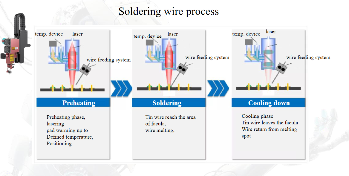
- Solder wire (0.3–0.8 mm): suits through-hole pins, wire-to-pad and repair work. Look for feed accuracy around ±0.1 mm and a feed-rate range from roughly 5 to 50 mm/s so you can scale wire volume to joint size.
Whatever the format, confirm the alloy and melting range against your component ratings: SAC305 at 217–220 °C, Sn63Pb37 at 183 °C, and bismuth-based low-temperature alloys around 138 °C. A machine that cannot hold a stable peak temperature at the low end of that range is a poor match for temperature-sensitive optical or sensor packages.
Why closed-loop temperature control decides your first-pass yield
Open-loop, time-and-power control is the most common reason a laser soldering system performs well in a demo and badly in production. Part-to-part variation in emissivity, pad size and copper mass changes how much heat actually reaches the joint. Specify a pyrometer or thermal sensor feeding a closed loop at roughly 1 kHz or faster, with these capabilities:
- Programmable profile: preheat, ramp, dwell and cool segments, with ramp rates typically in the 100–300 °C/s range for micro joints and lower for high-mass parts.
- Peak temperature control at 20–40 °C above the alloy liquidus, held within ±5 °C through the dwell window.
- Emissivity setting per product recipe, with thermocouple verification at commissioning — an emissivity error is the single most frequent cause of a machine running 30 °C hotter or colder than the recipe says.
- Per-joint data logging of the actual profile, exported to your MES, so a suspect lot can be traced to a specific joint and profile.
Intermetallic compound growth is the physical reason this matters: a well-controlled profile produces an IMC layer of roughly 1–3 µm. Too little heat gives an incomplete reaction and a weak joint; too much gives a thick, brittle IMC layer that fails thermal cycling even though the joint looks acceptable at incoming inspection.
What vision, motion and inline integration specs should you verify?
Ask for alignment and repeatability figures separately, because suppliers sometimes quote an excellent of the two. Typical expectations for production equipment:
- CCD vision alignment within ±10–25 µm, with fiducial recognition that works on low-contrast boards.
- Stage or gantry repeatability around ±5 µm, verified with a glass scale rather than a dial indicator.
- Throughput quoted as joints per hour at a stated profile, not as a maximum axis speed — 600–3,000 joints/hour is a realistic band depending on joint size and feed format.
- SMEMA-compatible infeed/outfeed, ESD-safe grounding, and an MES interface (SECS/GEM or an open protocol) if the line is already connected.
- Nitrogen shielding at the nozzle if you run lead-free alloys on high-reliability boards — it visibly reduces oxide-related voids and improves fillet formation.
How do you run an acceptance test before signing off?
Send 30–50 of your own boards or representative coupons and require the vendor to return cross-sections and X-ray data, not just good photographs. Your acceptance checklist should include: void rate under 10% on thermal pads by X-ray, IMC thickness of 1–3 µm on cross-section, pull or shear strength against the applicable IPC/JEDEC criterion, and a Cpk above 1.33 on peak joint temperature across the sample. Then run a 4–8 hour continuous run and check drift.
| Symptom you see | Likely cause | First troubleshooting step |
|---|---|---|
| Dull, cold-looking fillet | Peak temperature too low, ramp too fast, wrong emissivity | Verify pyrometer against a thermocouple on a test coupon; extend dwell |
| Voids above 15% | Flux outgassing, no nitrogen, excess paste volume | Add N₂ shielding; extend preheat; reduce deposited volume |
| Ball not released or feed jam | Clogged nozzle, worn feed mechanism, timing error | Clean or replace nozzle; check vacuum and feed-step calibration |
| Burn marks or lifted pads | Temperature overshoot, emissivity set too low | Re-tune the loop; cap maximum power; check optics focus |
| Placement drift beyond 50 µm | Camera calibration drift, weak fiducial contrast | Recalibrate vision; confirm fiducial definition on the panel |
FAQ
What does laser soldering equipment cost?
Benchtop or semi-automatic units generally start in the mid five figures; inline automated systems with ball feeding, closed-loop control and AOI typically run well into six figures depending on configuration, feeder count and integration scope. Treat any quote without a sample-board validation as provisional.
Can laser soldering replace reflow for a whole board?
Not usually. Laser soldering is a selective process for local joints, rework, heat-sensitive areas and connectors that reflow cannot reach. Most lines use reflow for the bulk of the board and laser soldering for the remainder.
How many joints per hour should I expect?
For 0.3–0.6 mm joints with ball feed, roughly 1–3 joints per second is realistic including vision alignment and profile dwell. Larger joints with high thermal mass take proportionally longer — always ask for throughput at your profile, not at maximum speed.
Is nitrogen mandatory?
No, but for lead-free alloys on automotive or medical boards it measurably reduces oxide formation and voiding. Ask for a side-by-side sample run with and without N₂ and compare X-ray void percentages before deciding.
Do we need AOI integrated into the machine?
If you cannot inspect the joint visually after the process — connector interiors, shielded areas, stacked assemblies — post-solder AOI on the same platform saves a separate handling step and catches fillet defects before the board moves downstream.
If you can share your joint dimensions, alloy, throughput target and a few sample boards, we can run a profile trial and tell you which configuration fits — and which specifications you can safely leave off the quote.