Application note · Coil winding & capacitor terminations
Laser Soldering Enamelled Wire Without Stripping: A Real Trial
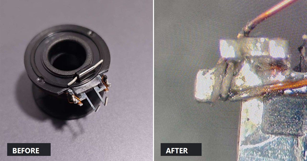
Coil terminals are the classic argument for stripping enamel before soldering: the enamel insulates the winding, so the same laser that melts the solder must burn through it before solder can reach copper. Can laser soldering enamelled wire skip stripping entirely? We tested it on a real automotive part — a wound coil assembly with enamelled leads and a capacitor on shared metal posts — using flux-cored SAC305 wire feeding. The part soldered. The joints also blackened.
The trial was run for an automotive-electronics manufacturer in China as a solderability check ahead of a production decision; everything below comes from that single test record.
The sample: one bobbin, two very different joints
The workpiece is a wound coil assembly, designated SOV120 in the report: a bobbin carrying a winding of enamelled copper wire, with the wire wrapped onto small metal posts on the lower flange. A capacitor sits on the same flange, its leads sharing the same posts. Two joint families in one fixture cycle:
- Coil joints. Enamelled copper wire wrapped around a post — with the insulation deliberately left on for this trial. That was the question being tested.
- Capacitor joints. Tinned component leads on the same posts. No insulation problem, but a placement problem: the capacitor is set by hand and not fixed.
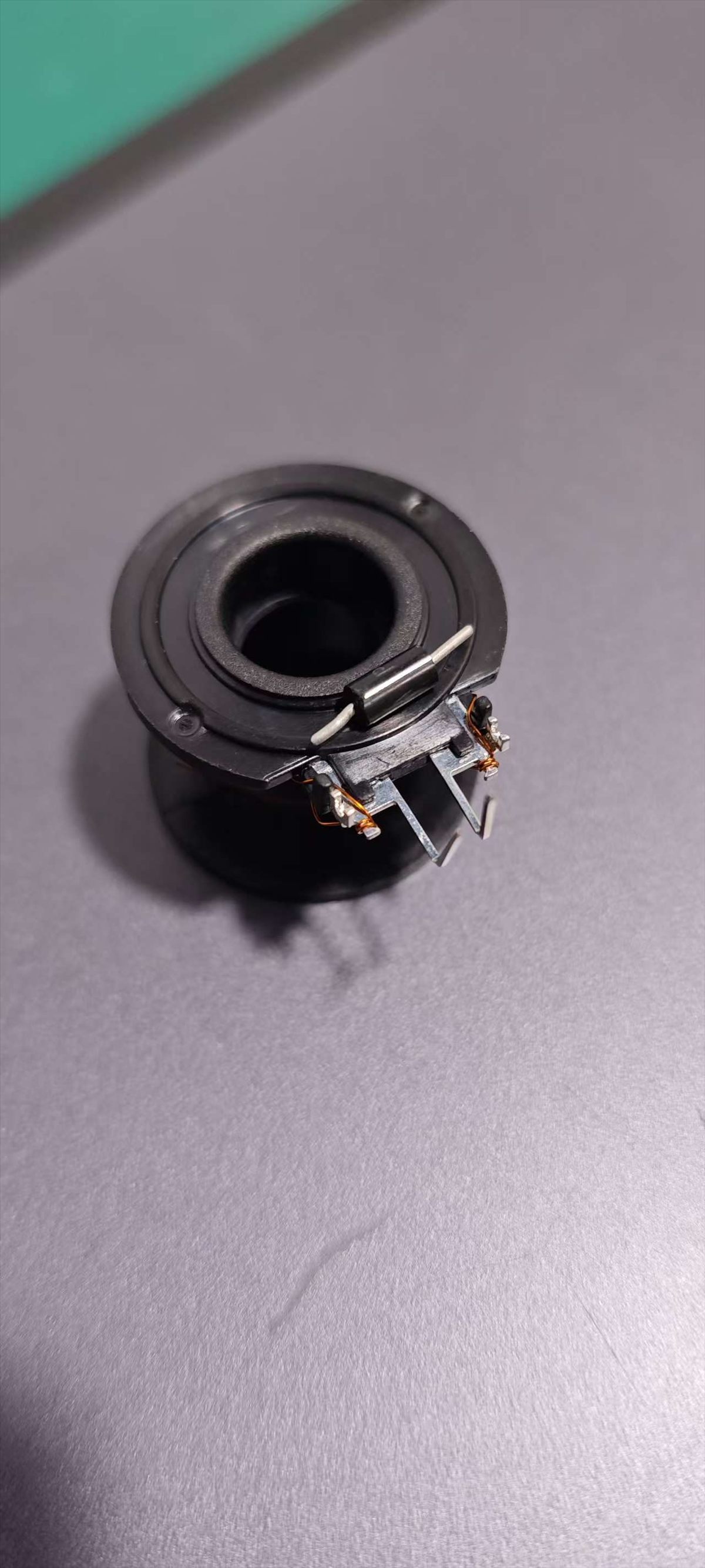
Three things make this part unforgiving for any heat source: the enamel blocks wetting until it is burnt away, the winding behind the posts conducts heat off the joint, and the plastic bobbin sits millimetres from the spot. The equipment side is covered in our complete guide to laser soldering; this note stays on the trial itself.
Trial setup and parameters
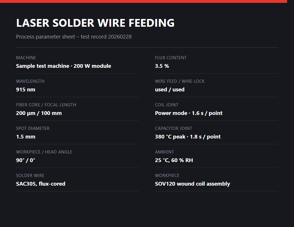
The trial used a 200 W fibre-coupled module at 915 nm with a 1.5 mm spot; solder came from a powered SAC305 wire feed with a wire lock. Coil joints ran in power mode, capacitor joints in closed-loop temperature mode. Values are exactly as recorded in the report.
| Laser / module power | 200 W |
|---|---|
| Wavelength | 915 nm |
| Fiber core diameter | 200 µm |
| Focal length | 100 mm |
| Spot diameter | 1.5 mm |
| Solder wire | SAC305, flux-cored |
| Flux content | 3.5 % |
| Wire feed / wire lock | Used / used |
| Workpiece angle / head angle | 90° / 0° |
| Ambient conditions | 25 °C, 60 % RH |
Joint 1 — coil terminals: solderable, but the enamel made it ugly
The coil joints ran in power mode at 1.6 s per point. The result split in two. Solderability: the report marks the coil OK — the laser burnt through the enamel and SAC305 wetted the copper where it could reach it. Appearance: the joints failed the eye test — the surface came out black and solder coverage over the wire bundle was poor.
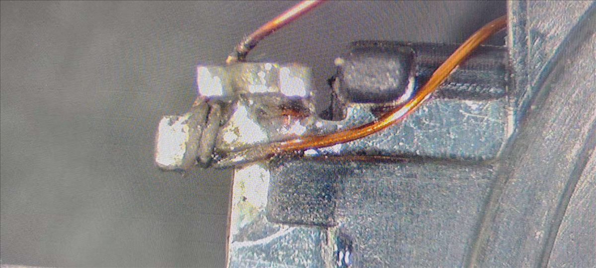
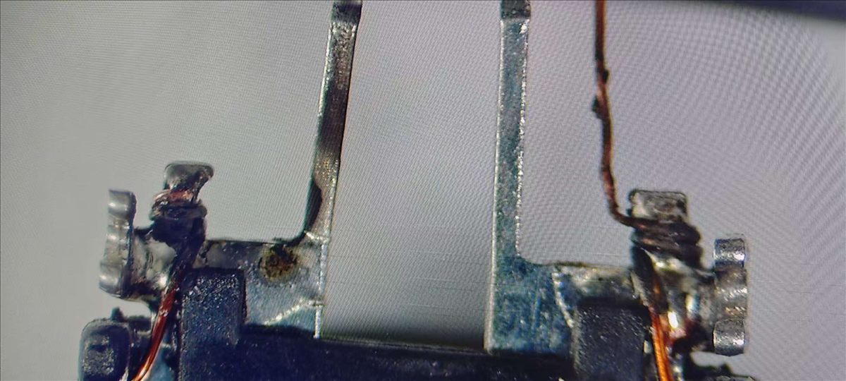
This is the predictable physics of soldering through enamel. Polyurethane insulation only breaks down under sustained heat, so the laser burns through it locally and the joint forms — but the decomposed enamel plus spent flux carbonizes right where the solder lands. Coverage suffers the same way: the wire only wets where the beam reached, while the wrapped bundle behind the post stays insulated. The report's verdict: strip the enamel before soldering — stability and appearance both improve.
What did not fail is equally telling: the 1.6 s cycle and the wire feed. The consumable is our lead-free solder wire range, and the 3.5 % flux core held up even against burnt enamel.
Joint 2 — capacitor terminals: the process worked, the fixture didn't
The capacitor joints ran in closed-loop temperature mode with a peak of 380 °C and a single-point time of 1.8 s. Solderability was OK. The capacitor leads are bare tinned copper, so there was no insulation to defeat — the loop held the joint at peak while the wire feed delivered solder, which is where closed-loop temperature control earns its keep.
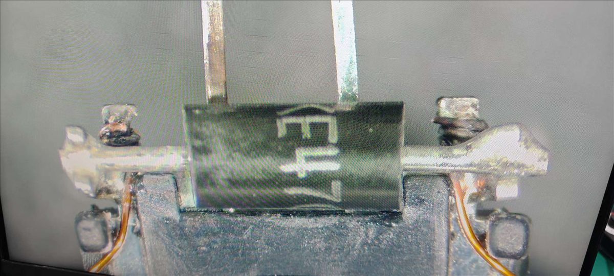
The finding that matters is mechanical. The capacitor is placed by hand and not fixed, so during soldering it can shift — the report flags movement, even detachment, as a live risk. A moving component drags the joint with it: the spot no longer lands where the program expects. No parameter tuning fixes that. The report recommends adding a clamping function on the jig — the cheapest change, and the one that unlocks everything else.
The two joint families side by side
| Joint family | Coil (enamelled wire) / Capacitor (tinned lead) |
|---|---|
| Heating mode | Power mode / Temperature mode |
| Peak / process time | Power mode, 1.6 s per point / 380 °C peak, 1.8 s per point |
| Insulation at the joint | Enamel left on / None |
| Solderability | OK / OK |
| Issue found | Blackened surface; poor coverage of the wire bundle / Position unfixed; shift and detachment risk |
| Report recommendation | Strip the enamel before soldering / Add clamping on the fixture |
Read together, the rows tell one story: the laser process is not the bottleneck on this part. One joint is limited by surface condition, the other by mechanical repeatability — both fixes sit upstream of the machine.
What we would change before production
The report is explicit that parameters, joint appearance and cycle time all still have room to improve. Four changes, in order:
- Strip the enamel at the wrap. This is the report's own recommendation and the highest-value one. Stripping defines the exact window where wetting can happen, so coverage over the bundle becomes repeatable, and it removes the carbonized layer that caused the blackening — exactly what a proper quality inspection routine would flag under discolouration criteria.
- Add capacitor clamping to the jig. A pocket or hold-down that fixes the capacitor position turns the detachment risk into zero. Until that exists the process cannot be qualified, because the worst failure mode happens under the spot where nobody can see it.
- Re-baseline the cycle after stripping. With enamel no longer consuming part of the energy budget, the coil joint should reach wetting in less than the recorded 1.6 s. Re-run the trials rather than carrying the old number forward.
- Write the acceptance criteria before scaling up. Decide what discolouration is acceptable post-strip, what minimum solder coverage the wrap must show, and inspect against that. This part class — winding terminations on automotive assemblies — sits in the same application family as our vehicle radar soldering line.
A checklist for your own enamelled-wire trial
- Decide the stripping question first — every other parameter is downstream of it.
- Solder through enamel and you get blackening and reduced coverage; budget inspection time for it.
- Use powered wire feed with a wire lock for wrapped terminations — hand-feeding a moving target does not hold.
- Run temperature mode, not power mode, on joints whose placement varies between parts.
- Fix every loose component before tuning; a clamp is cheaper than any parameter study.
- Record ambient conditions — this trial ran at 25 °C and 60 % RH — so baselines stay comparable.
FAQ
Can you laser solder enamelled wire without stripping the insulation?
You can — this trial proves the joint forms. The enamelled coil wire soldered OK in power mode at 1.6 s per point. But the surface came out black and coverage over the wire bundle was poor: solder only wets where the laser burnt the enamel away. The report's recommendation is to strip the wire first.
Why do solder joints on enamelled wire turn black?
The enamel is an insulator, so the laser must burn through it before solder wets the copper. What it leaves behind — decomposed enamel plus spent flux — carbonizes while the solder is molten. In this trial the blackening appeared exactly on the joints where the enamel was left on.
Should coil and capacitor joints run in power mode or temperature mode?
Here the coil joints ran in power mode and the capacitor joints in closed-loop temperature mode at a 380 °C peak. The capacitor joints came out cleaner — no insulation to defeat and the loop held the peak. For joints whose placement varies between parts, temperature mode is the safer start.
How do you stop a capacitor shifting during laser soldering?
Fix it mechanically. With the capacitor only hand-placed, it could shift or detach during soldering; the report recommends adding clamping on the jig. No laser parameter compensates for a component that moves under the spot.
How long does one laser wire-fed joint take?
1.6 s per point on the coil joints and 1.8 s on the capacitor joints, as single-point process times. The report notes cycle time still has room to improve — and a stripped-wire coil joint should come in shorter.
The one-line takeaway: laser soldering can close an enamelled-wire joint without stripping — but "solderable" and "production-ready" are different verdicts. Strip the wire, clamp the capacitor, and the same machine looks like a different process.
Have coil terminations that blacken or components that wander?
Send us the bobbin, the wire spec and the component layout. We will run the same trial on our laser soldering platform and return a parameter sheet with before-and-after photos, the way this note was built.
Source: internal test record 20260228, February 2026 — laser solder wire feeding, 200 W / 915 nm, 1.5 mm spot, SAC305 flux-cored wire (3.5 % flux), 25 °C / 60 % RH. No parameter screenshot in the report; the parameter image was redrawn from the printed values. All data, photographs and conclusions come from that single test record. Customer described by industry only.