


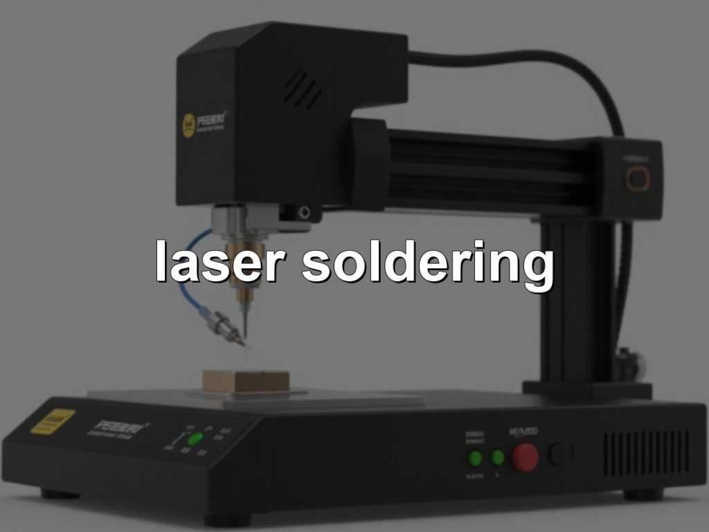
Laser soldering uses a focused diode laser beam as the heat source to reflow a single joint — the beam is delivered through a fiber, focused to a 0.3–3 mm spot, and modulated in real time by a closed-loop temperature sen…
Laser soldering uses a focused diode laser beam as the heat source to reflow a single joint — the beam is delivered through a fiber, focused to a 0.3–3 mm spot, and modulated in real time by a closed-loop temperature sensor so the solder follows a programmed profile instead of a fixed iron temperature. Because heat is applied only where the beam lands, joints on thick copper, heat-sensitive assemblies and fine-pitch parts can be soldered with a heat-affected zone of roughly 1–2 mm and cycle times of 0.5–3 s per joint. This article covers how the process works, how to choose between solder ball, paste and wire feeding, which parameters to lock first, and how to qualify and troubleshoot the joint.
How does a laser actually heat a solder joint?
Energy is absorbed at the surfaces the beam strikes — pad, lead, pin and the solder itself — and conducts into the joint. The absorption coefficient of copper and solder is wavelength dependent: 808–976 nm diode sources couple noticeably better into bare copper than 1064 nm, which is why most production soldering heads use diode wavelengths rather than Nd:YAG. Spot diameter is usually set to 0.6–1.2× the pad width so the joint reaches reflow while the neighbouring component body stays below its damage threshold.
The control loop is what separates laser soldering from a simple spot heater. A pyrometer or two-colour sensor samples the joint at roughly 1 kHz; the controller compares that reading with a stored profile (optional preheat, ramp, peak dwell above liquidus, cool-down) and adjusts laser power accordingly. Two practical consequences:
- Emissivity must be calibrated per surface. Fresh solder, oxidised copper and gold-plated pads read differently. Correlate the pyrometer against a contact thermocouple on the first article, then keep that calibration with the recipe.
- Power is an output, not a setpoint. Two boards with different copper mass will see different power for the same profile — that is the point, and it is why the process tolerates board-to-board variation better than a fixed-time hot bar schedule.
Nitrogen shielding (coaxial or side delivery, typically 5–20 L/min, O₂ below 1000 ppm) is usually needed to keep the joint bright and allow lower-activity flux, which matters on assemblies that cannot be cleaned.
Which solder feed format fits your joint — ball, paste or wire?
The feed format determines your joint volume repeatability, your flux strategy and how much of the cycle is mechanical handling. The three options are not interchangeable on the same joint.
| Feed format | Typical size | Best suited to | Watch-outs |
|---|---|---|---|
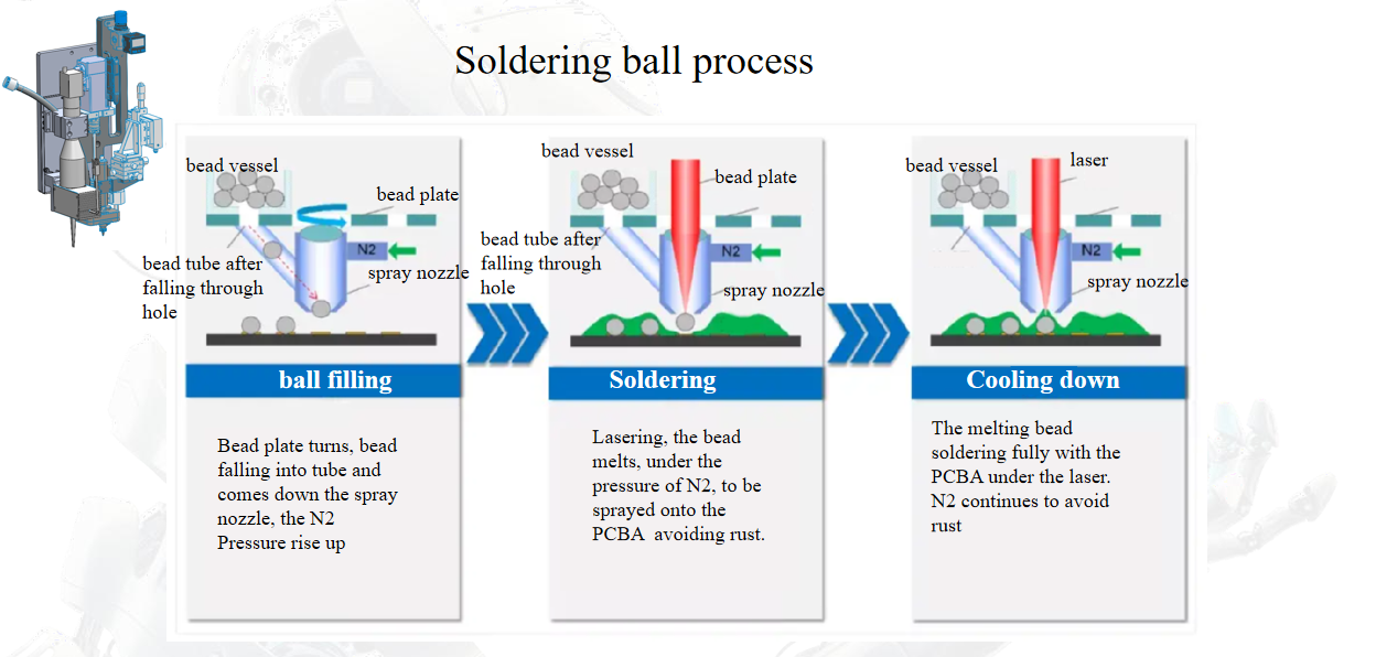
| Solder ball | 0.20–0.76 mm diameter | Through-hole pins, connectors, BGA/CCGA reball, joints where a fixed solder volume is mandatory | Requires flux deposition and accurate ball placement; ball must land on the joint centre, not the lead shoulder |
| Solder paste | Type 4–6 powder (15–45 µm) | Fine-pitch SMT pads, dispensed dots of 0.2–0.5 mm, mixed-technology boards | Flux vehicle must be driven off before peak; slump and spatter are the usual defect sources |
| Solder wire | 0.3–1.0 mm, flux-core or solid | Wire-to-pad, magnet wire and coil terminations, shield cans, ground tabs, rework | Feed rate and wire-tip position drift with feeder wear; wire must contact the joint, not the beam path |
For a joint with a defined volume requirement — a connector pin in a plated hole, for example — ball feeding gives the most repeatable result because volume is fixed by the ball diameter. For pad-to-pad work, dispensed paste is more flexible. Wire is the practical choice where solder must be added to an existing termination, such as a coil winding on a terminal post.
Which process parameters should you lock down first?
Start from the alloy, not the equipment. Peak joint temperature should sit 25–40 °C above liquidus, measured at the joint, not inferred from laser power. The window below is a realistic starting point for a first article; refine it with cross-sections and pull tests.
| Parameter | Typical starting window | Why it matters |
|---|---|---|
| Peak joint temperature | SAC305: 240–250 °C; Sn63Pb37: 205–215 °C | Too low gives cold joints; too high burns flux and grows intermetallic |
| Ramp rate | 50–150 °C/s (slower, 30–50 °C/s, below 150 °C on paste) | Controls flux outgassing and spatter |
| Time above liquidus | 0.5–2.0 s | Wetting and void escape versus intermetallic growth |
| Optional preheat | 100–150 °C for 1–3 s | Reduces thermal shock on thick boards and large copper planes |
| Spot diameter | 0.6–1.2× pad width | Wetting coverage without heating adjacent parts |
| Laser power (closed loop) | 10–100 W, joint dependent | Determined by absorptivity and copper mass; log it, do not fix it |
| Nitrogen flow | 5–20 L/min, O₂ <1000 ppm | Wetting, dross and residue colour |
Two process details that cause most first-article failures: the beam is aimed at the pad rather than the joint interface, and the solder feed arrives after the peak instead of during ramp. Solder should be molten and wetted before the peak dwell ends, otherwise the profile is simply heating an empty pad.
How do you qualify and inspect a laser-soldered joint?
Qualification is a first-article exercise followed by a smaller routine check. A workable acceptance set:
- Thermal verification: contact thermocouple at the joint agrees with the pyrometer reading within ±10 °C across three consecutive parts.
- Visual and AOI: concave fillet, wetting angle under 90°, continuous coverage of the pad and lead, no charred flux ring, no solder wicking into flex, connector housing or stranded wire beyond the specified length (IPC-A-610 fillet criteria apply).
- Cross-section: intermetallic layer 1–4 µm, continuous, no Kirkendall voids or unconsumed flux pockets at the interface.
- X-ray: voiding under thermal pads typically held below 25% area; through-hole fill per the drawing.
- Mechanical: pull or shear to a baseline established from the first qualified lot, plus periodic re-checks after any feeder, nozzle or beam-delivery change.
- Thermal damage check: temperature rise at 2 mm from the joint stays within the neighbouring component’s rating; plastics show no gloss change or deformation.
Routine production checks are simpler: laser power trend per joint, weekly spot-profile check, gas flow and nozzle condition, and AOI on every part. A drifting power trend on a stable recipe usually means window contamination or fiber connector wear, not a recipe problem.
Troubleshooting: what do the common defect symptoms tell you?
| Symptom | Likely cause | Action |
|---|---|---|
| Dull, grainy fillet; incomplete melting | Power or dwell short, spot off joint, emissivity calibration error | Verify with thermocouple, re-teach spot position, extend time above liquidus |
| Solder spatter and micro-balls | Ramp too fast, moisture in paste or board, wire feed overshoot | Slow the ramp below 150 °C, add preheat, check storage and feed timing |
| Voids in the joint | Trapped flux volatiles, short time above liquidus, contaminated pad | Extend dwell, clean or plasma-treat pads, confirm nitrogen coverage |
| Dark residue or burnt flux ring | Peak temperature excessive, gas off, overshoot on small joints | Reduce peak 10–20 °C, check gas at the nozzle, review loop tuning |
| Non-wetting or dewetting | Oxidised pad, insufficient flux activity, peak too low | Check pad shelf life and plating, adjust flux volume, raise peak within window |
| Melted or deformed adjacent plastic | Spot too large, beam clipping, no shielding | Reduce spot, defocus, add a shield or re-sequence joints |
| Inconsistent ball or wire feed | Feeder wear, tube misalignment, wire diameter tolerance | Measure feed length per cycle, replace worn tube, verify incoming wire spec |
FAQ
Is laser soldering the same as laser welding?
No. Soldering melts a filler alloy below roughly 450 °C and leaves the base metal solid; welding fuses the base metal itself. They use different equipment, different metallurgy and different inspection criteria, and should never be specified interchangeably.
What cycle time can I expect per joint?
Heating and reflow typically take 0.5–3 s, dominated by copper mass and the profile you need. Ball or paste placement and indexing usually add more time than the laser itself, so inline module layout matters as much as beam power.
Can laser soldering handle through-hole connectors on a mixed-technology board?
Yes — point-by-point soldering of connector pins is one of the common applications, particularly where a reflow oven would stress heat-sensitive parts nearby or where the board is too thick for a consistent iron dwell. Ball feeding gives the most repeatable fill.
Do I need special solder or flux?
Standard SAC305 or SnPb balls, paste and wire work; what changes is the flux strategy and the atmosphere. Lower-activity, no-clean fluxes usually become viable once nitrogen shielding is in place, which simplifies cleaning requirements.
How do I confirm joint temperature in production without a thermocouple on every part?
Calibrate the pyrometer against contact thermocouples on the first article for each joint type and surface finish, store that calibration in the recipe, and re-verify whenever pad plating, solder alloy or flux changes.
If you share your joint geometry, alloy and cycle-time target, our engineers can propose a beam, feed and shielding configuration for your specific assembly.