


Closed-loop temperature control in laser soldering means the machine measures the joint temperature in real time with a pyrometer and continuously modulates laser output power so the joint follows a programmed reflow pro…
Closed-loop temperature control in laser soldering means the machine measures the joint temperature in real time with a pyrometer and continuously modulates laser output power so the joint follows a programmed reflow profile, rather than heating on a fixed power curve. Because laser heating is fast and part-to-part absorptivity varies, open-loop power control tends to produce a cold, poorly wetted joint on one unit and charred flux on the next; closed-loop control brings peak temperature repeatability into the ±5–10 °C range at production cycle times of 0.5–3 s.
What exactly does the loop control, and where does the sensor sit?
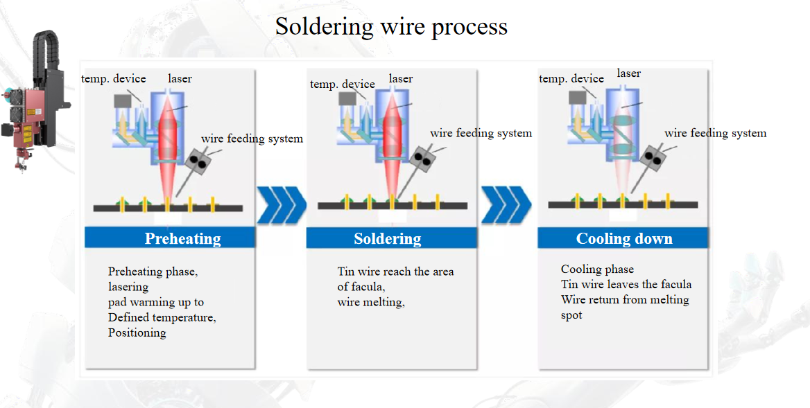
A production-grade closed-loop laser soldering head has three elements working together:
- Heat source: a diode laser at 915 nm, 980 nm or 1470 nm, typically 10–120 W at the work surface, delivered through a focused spot of 0.3–2.0 mm.
- Sensor: a fast pyrometer viewing the joint through a dichroic beamsplitter, so the measurement spot is coaxial with — and normally the same size as — the laser spot.
- Controller: a PID or model-based loop sampling at 1–5 kHz, with total loop latency (sensor response + processing + driver) of roughly 50–200 µs, driving the laser via 0–10 V analogue or high-resolution PWM.
Two details separate genuine closed-loop control from marketing language. First, the sensor must measure the joint, not the surrounding substrate — if the pyrometer spot is wider than the pad, it averages in cold laminate or ceramic and the loop consistently under-heats. Second, the profile must be temperature-driven. Some heads run a fixed power ramp and only use the pyrometer as an over-temperature cut-off; that is a safety interlock, not closed-loop profile control, and it will not compensate for emissivity or absorptivity differences between parts.
Which temperature sensor fits your joint size and material?
Sensor choice drives both accuracy and maintenance interval. The table below reflects typical production behaviour:
| Sensor type | Spectral band | Response time | Spot size | Best suited to | Main limitation |
|---|---|---|---|---|---|
| Single-colour pyrometer (InGaAs) | 1.2–1.6 µm | 1–5 ms | 0.3–1.5 mm | General solder ball and paste joints, connector pins | Reads low on shiny gold/Ni pads or bare copper |
| Two-colour (ratio) pyrometer | Two close bands, 1.0–1.7 µm | 1–10 ms | 0.5–2 mm | Reflective pads, mixed emissivity, wire-fed joints | Both wavelengths must fill the spot; higher cost |
| Thermopile / LWIR detector | 8–14 µm | 10–50 ms | 1–3 mm | Larger joints, slower profiles, low-temperature solders | Too slow for sub-second laser ramps |
| Coaxial through-lens pyrometer | Matched to laser optics | 1–5 ms | Matched to laser spot | Micro joints, 0201/0402, fine-pitch connector leads | Beamsplitter alignment drifts if optics are disturbed |
| Contact thermocouple | — | 20–100 ms | Point contact | Calibration and profile verification only | Cannot be used as production feedback |
For SAC305 and other lead-free alloys, short-wavelength (near-IR) pyrometers are preferred because liquid solder has usable signal intensity there and the measurement spot can be made small. On gold-plated or bare-copper pads, emissivity can drop well below the value assumed during calibration, which is the single most common reason a loop reads 15–30 °C lower than the true joint temperature. Use a ratio pyrometer, or calibrate emissivity per pad finish and store it in the recipe.
How do you set a closed-loop profile for a solder ball or paste joint?
Laser soldering compresses a reflow profile into a few hundred milliseconds, so each segment must be defined explicitly. Typical windows:
| Alloy | Melting range | Preheat / soak | Peak temperature | Ramp rate | Time above liquidus |
|---|---|---|---|---|---|
| SAC305 | 217–220 °C | 130–170 °C, 100–300 ms | 235–245 °C | 100–250 °C/s | 0.5–2.0 s |
| Sn63Pb37 | 183 °C | 110–150 °C, 80–250 ms | 200–215 °C | 100–250 °C/s | 0.4–1.5 s |
| SnAg3.0Cu0.5 (fine powder paste) | 217–221 °C | 140–175 °C, 150–350 ms | 235–250 °C | 80–200 °C/s | 0.6–2.5 s |
| SnBi low-temperature | 138–140 °C | 90–120 °C, 100–250 ms | 155–170 °C | 80–180 °C/s | 0.5–2.0 s |
Practical settings that make the loop behave:
- Limit the ramp with a setpoint slope, not a power ceiling. A 150 °C/s slope limit on a 0.4 mm ball avoids overshoot on small thermal mass while still finishing inside 1 s.
- Cap the integrator. Anti-windup is essential because the laser saturates at the start of every cycle; without it, the loop overshoots 10–20 °C on the second and third joint of a burst.
- Set an over-temperature trip 15–20 °C above peak and a dT/dt trip, so a dropped part or blocked beam is caught before the pad or flex is damaged.
- Define cooling. Forced air or a short dwell at 30–50% power after TAL keeps the joint from being held hot while the head indexes, which otherwise coarsens the intermetallic layer.
Why does the measured temperature drift from the real joint temperature?
Use the symptom table below as a first-line diagnostic before touching PID gains:
| Symptom | Likely cause | Verification step | Corrective action |
|---|---|---|---|
| Incomplete wetting, dull fillet, but peak temperature reads correct | Sensor reading high relative to joint — contaminated window or wrong emissivity | Attach a 0.1 mm K-type thermocouple to the joint and compare peak values | Clean or replace protective window; re-run emissivity calibration on that pad finish |
| Overshoot of 10–25 °C, flux charring, solder beading | PID proportional/integral gains too aggressive or sampling too slow | Log the temperature trace at 1 kHz and inspect the first 100 ms | Reduce P by 30–50%, add anti-windup, raise sample rate |
| Reading varies joint-to-joint by more than 15 °C | Pyrometer spot larger than joint, averaging substrate; or ball/paste volume variation | Check spot geometry with alignment target; weigh or measure deposited paste | Reduce spot via aperture, lock paste deposit volume, verify feeder repeatability |
| Gradual downward drift over a shift | Flux volatiles condensing on the window or lens | Compare reading against thermocouple at start and end of shift | Add window purge air, shorten cleaning interval, log calibration check hourly |
| Loop oscillates or hunts at setpoint | Loop latency too high relative to joint thermal mass | Measure driver response with a step command | Use feed-forward power term, reduce loop gain, check driver bandwidth |
What acceptance checks confirm the loop is actually working?
- Thermocouple cross-check: peak temperature agreement within ±8–10 °C across three joint types, repeated at the start and end of each shift.
- Repeatability: 30 consecutive joints on the same pad, peak-temperature spread under 10 °C, and process capability CpK ≥ 1.33 against the profile limits.
- Cross-section: intermetallic layer 1–4 µm for SAC305; above roughly 6 µm indicates the loop is holding the joint hot too long.
- Wetting and voiding: wetting angle under 90°, voiding within the limits of IPC J-STD-001 / IPC-A-610 class applicable to the product; pull or shear strength consistent with the qualified baseline.
- Post-solder AOI: fillet shape, solder volume and position verified on highly of joints, with the temperature trace archived per part for traceability in automotive and semiconductor packaging builds.
FAQ
What sampling rate do I need for laser soldering?
At least 1 kHz, and 2–5 kHz for ball diameters below 0.4 mm or cycle times under 1 s. Below 500 Hz the loop reacts too late to the initial ramp and overshoot becomes difficult to eliminate.
Can closed-loop control be used with solder wire feeding?
Yes. The loop controls the joint temperature; the wire feeder is triggered by position or by the temperature trace reaching the preheat setpoint. The one requirement is that wire feed rate be synchronized with the ramp, otherwise the added cold mass can pull the joint below liquidus mid-cycle.
Does closed-loop control remove the need for thermocouple profiling?
No. The pyrometer measures what it sees, and what it sees depends on emissivity and spot alignment. Thermocouple verification remains the reference method for initial qualification and for periodic drift checks.
Why does the pyrometer agree with the thermocouple at installation but not three weeks later?
Almost always window contamination from flux volatiles, or a shift in beamsplitter alignment after a head crash or tool change. Clean the window, re-run the alignment target, then re-check with a thermocouple before adjusting any controller gains.
Is closed-loop control worth it for joints with very small thermal mass?
It is most valuable there. Small joints heat and cool in tens of milliseconds, so power-mode control leaves no margin; the loop is what keeps peak temperature inside a 10 °C band while still completing the joint in under a second.
If you share your pad finish, alloy and joint geometry, our process engineers can map a starting closed-loop profile and sensor configuration for your line.