


Laser soldering machine is a selective soldering system that uses a focused laser beam — typically a 915 nm or 976 nm diode laser, sometimes a 1064 nm fiber source — as the heat source to melt solder ball, solder paste o…
Laser soldering machine is a selective soldering system that uses a focused laser beam — typically a 915 nm or 976 nm diode laser, sometimes a 1064 nm fiber source — as the heat source to melt solder ball, solder paste or solder wire at a specific joint, while a pyrometer measures the joint temperature in real time and closes the loop on laser power. Instead of heating a whole board in a reflow oven, it delivers 30–150 W into a 0.3–2.0 mm spot, ramps the joint at 50–150 °C/s, holds it 30–50 °C above the alloy liquidus for 0.5–3 s, and finishes a single joint in roughly 1–5 s. That combination of localised heat and tight temperature control is what makes it usable for fine-pitch connectors, camera modules, sensor pins and other assemblies that cannot survive a second full reflow pass.
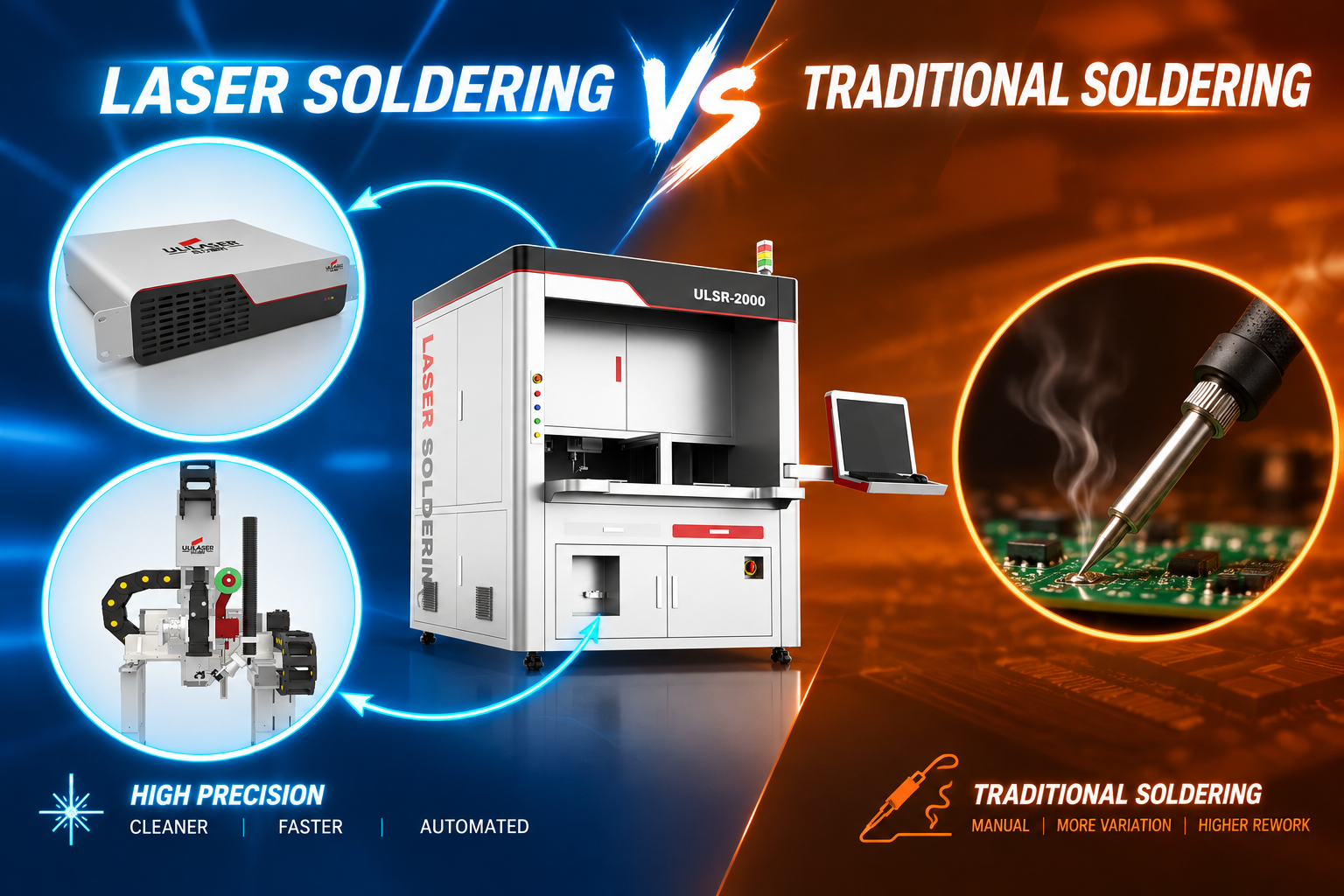
How does a laser soldering machine deliver heat and solder to a joint?
A production machine is really four subsystems working in sequence, and a weakness in any one of them shows up as a joint defect:
- Beam delivery. A diode laser is coupled to the work area either by a galvo scanner (fast, 10–30 ms repositioning, ideal for multiple joints inside one field) or by a gantry with a focusing head (larger travel, heavier parts, wire feeding). Spot size is set by focus height; a 0.3 mm spot concentrates energy for micro joints, a 1.5–2.0 mm spot spreads it for connector pins and through-hole barrels.
- Solder feeding. Solder ball dispensing (0.15–0.76 mm spheres) suits BGA pads, connector tails and fine-pitch arrays with no paste printing. Paste dispensing or jetting (0.1–0.3 mm deposits) suits mixed footprints and gives volume control per pad. Wire feeding (0.3–1.0 mm flux-cored wire) suits through-hole connectors and larger terminals.
- CCD vision alignment. A coaxial camera locates the pad or pin and offsets the beam; typical position repeatability needs to be within ±0.05 mm, because at a 0.4 mm pitch a 0.1 mm drift already puts heat on the neighbour.
- Closed-loop temperature control. The pyrometer reads the joint, not the laser, and the controller modulates power in millisecond steps to follow a programmed ramp-hold profile. Good systems hold peak temperature within ±5–10 °C; that is what prevents both cold joints and laminate damage on the same panel.
Which feeding method fits your joint — ball, paste or wire?
Selection is driven by pad geometry and alloy, not by preference. Use the table as a first filter, then confirm with a trial build.
| Feeding method | Typical size range | Best-fit joints | Main constraint |
|---|---|---|---|
| Solder ball | 0.15–0.76 mm sphere | BGA pads, fine-pitch connectors, camera module pads, package-to-board | Ball placement accuracy; limited alloy availability at very small sizes |
| Solder paste | 0.1–0.3 mm deposit | Mixed SMD footprints, shield frames, small terminals, rework of paste-printed pads | Flux volatiles cause spatter if the ramp is too aggressive; deposit volume drifts with needle wear |
| Solder wire | 0.3–1.0 mm flux-cored | Through-hole connectors, wire-to-terminal, taller terminals, larger thermal mass | Feed timing must match the melt window; wire must retract cleanly to avoid a frozen tail |
Which process parameters should be locked before releasing a recipe?
Recipes that are copied between machines without re-verification are the most common source of drift. Lock these values, record them in the control plan, and re-qualify whenever the laser module, lens or feeder is swapped:
| Parameter | Typical setting | What it controls |
|---|---|---|
| Preheat / soak temperature | 100–150 °C, 0.5–2 s | Drives off flux solvent, reduces thermal shock, improves wicking into barrels |
| Ramp rate | 50–150 °C/s | Too fast = spatter and solder balls; too slow = oxidation and long cycle |
| Peak temperature | Liquidus + 30–50 °C (SAC305 ≈ 245–265 °C) | Wetting and fillet formation; excess damages laminate and components |
| Time above liquidus | 0.5–3 s | Intermetallic formation and void escape; too long coarsens the joint |
| Spot diameter | 0.3–2.0 mm | Energy density and heat-affected zone; should roughly match pad + lead footprint |
| Nitrogen flow / O₂ | 10–25 L/min, O₂ typically below 1000 ppm | Oxide-free wetting, especially on OSP and bare-copper finishes |
Why do laser solder joints fail, and how do you troubleshoot them?
Most field complaints map to a small set of symptoms. Work through them in this order — heating, then material, then mechanics:
- Dull, grainy or cold joint. Confirm pyrometer calibration against a contact thermocouple first, then check spot centring and whether dwell time is being cut short by the motion program. A joint that reads 250 °C on the controller but looks cold usually means the pyrometer is seeing the lead, not the solder.
- Solder balls and spatter around the joint. Almost always a ramp issue or moisture. Slow the first 100 ms of the ramp, bake moisture-sensitive parts and paste, and check that flux is not being pre-vaporised by a beam that arrives before the solder is in position.
- Tombstoning or component shift. Uneven heating between the two pads. Balance spot position and power on both joints, verify placement force, and check that the second joint is not being heated through an already-solidified first joint.
- Laminate blistering, pad lift or component cracking. Peak temperature or energy density is too high. Reduce power, widen the spot, shorten dwell — do not simply shorten dwell if the joint is also cold; that points to a focus problem instead.
- Voids in thermal pads or BGA joints. Trapped volatiles. Extend time above liquidus slightly, add or adjust preheat so the flux activates before the peak, and confirm the pad finish is not heavily oxidised.
- Solder not wicking into a through-hole. Insufficient preheat or barrel thermal mass beyond the spot’s reach. Raise preheat, increase spot size, or switch from ball to wire feeding with a longer melt window.
Which acceptance checks prove the process is in control?
- Visual and AOI: fillet shape, wetting angle, no bridging, no solder balls, per IPC-A-610 / J-STD-001 criteria agreed with your customer.
- X-ray: void percentage on thermal and ground pads (commonly held to ≤25%), head-in-pillow on BGA, barrel fill on through-hole.
- Destructive: pull or shear test on a sampled joint per shift, plus periodic cross-section to check intermetallic thickness and grain structure.
- In-process: pyrometer profile logged per joint, laser power trending, and a daily verification coupon on a dummy board to catch lens contamination and focus drift.
FAQ
Can a laser soldering machine solder through-hole connectors?
Yes, usually with flux-cored wire or a larger ball and a 1.0–2.0 mm spot. The limiting factor is barrel thermal mass: deep, plated barrels need more preheat and a longer melt window than surface pads.
How fast is it compared with an iron or hot-air rework station?
A single joint is typically 1–5 s including motion, and galvo systems can hit several joints inside one field without repositioning. The real gain is consistency — every joint gets the same logged profile, which hand soldering cannot deliver.
Is nitrogen mandatory?
Not always, but it is standard for OSP and bare-copper finishes and for any joint where appearance and wetting angle are inspected. Expect to run below roughly 1000 ppm O₂ at the joint.
Is laser soldering the same as laser welding?
No. Soldering melts a filler alloy below about 450 °C and the base metal stays solid; welding fuses the base metal itself. They use different power densities, different optics and different quality standards, and the equipment is not interchangeable.
Can it replace a reflow oven for a whole board?
Generally not. Its value is selective and local — joints that cannot take another reflow cycle, heat-sensitive parts nearby, or rework and touch-up where a repeatable, logged profile matters.
If you share your pad geometry, alloy and cycle-time target, our application engineers can recommend a feeding method and beam configuration and run a sample build with you.