


A laser soldering station is a benchtop, non-contact soldering system that focuses a near-infrared diode laser onto a specific pad-and-lead interface and holds the joint temperature in closed loop with a pyrometer, feedi…
A laser soldering station is a benchtop, non-contact soldering system that focuses a near-infrared diode laser onto a specific pad-and-lead interface and holds the joint temperature in closed loop with a pyrometer, feeding solder wire, paste or preforms as the filler. It is typically chosen where a soldering iron or hot-air nozzle cannot reach, cannot heat fast enough, or would put too much thermal and mechanical load on the part — fine-pitch connectors, 01005/0201 passives, shielded RF modules, flex-to-board joints and heat-sensitive sensor assemblies. Because the heat is delivered optically and switched off in milliseconds, the surrounding board and nearby components stay far cooler than with contact methods.
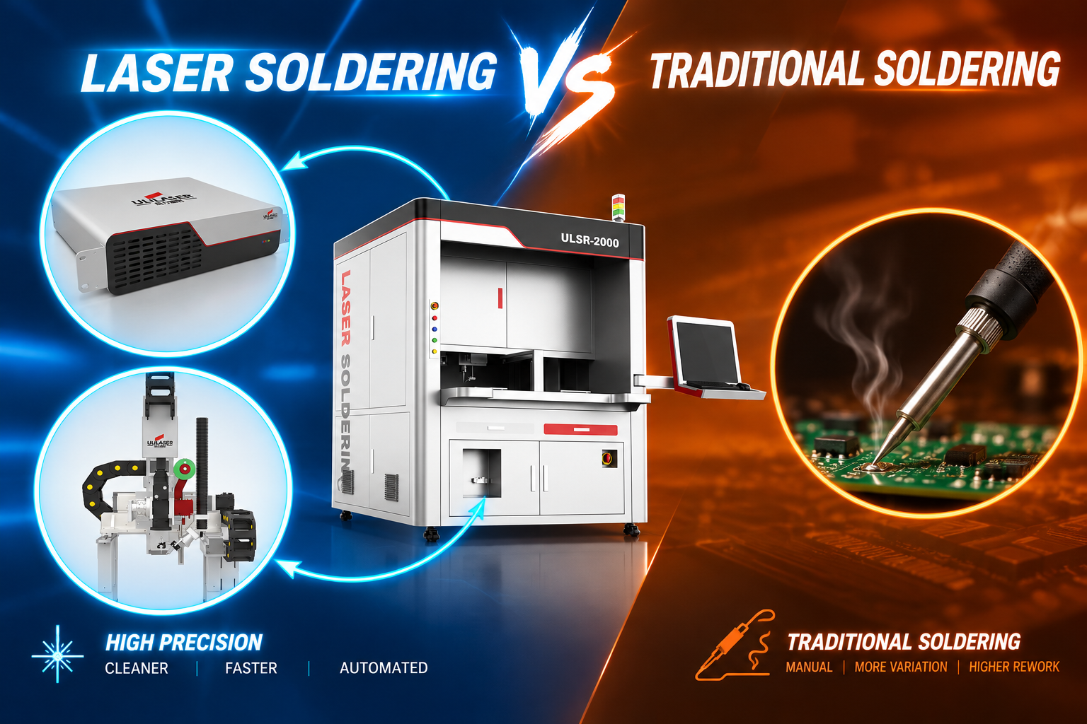
How does a laser soldering station differ from an iron or hot-air station?
The differences are physical, not cosmetic, and they drive how you set up the process:
- Heat delivery: an iron transfers heat by conduction through a tip in contact with the joint; a hot-air station by convection over a broad area. A laser delivers photon energy to a spot of 0.3–2 mm, heating the pad and lead interface preferentially, with the beam switched on for 0.2–2 s.
- No mechanical load: nothing touches the joint during reflow, so 0.3 mm-pitch leads and thin flex tails are not pushed sideways. This is the main reason laser stations appear in connector and sensor rework.
- Ramp rate: 50–200 °C/s is normal, against roughly 5–20 °C/s for contact heating. Fast ramp means less time at temperature for the part, but it also means thermal shock control and an accurate pyrometer matter more.
- Temperature control: a coaxial pyrometer (single-colour at 1.6–2.4 µm, or two-colour for varying emissivity) reads the joint and modulates laser power at 1–10 kHz. Setpoints of 300–400 °C for SAC305 are typical, with ±10–20 °C control at the joint.
- Atmosphere: most stations add local nitrogen shielding at 5–20 L/min to suppress oxidation during the fast ramp, since there is little flux activation time.
Note that this is a soldering process — filler metal reflowed onto a metallised pad. It is not laser welding (fusion of base metal), and the two require different equipment, optics and safety classes.
Which laser wavelength, power and spot size do you need?
Near-infrared diode sources (808, 915, 976, 980 nm) are the standard for solder because tin-based alloys and copper absorb reasonably well there. CO₂ lasers at 10.6 µm are a poor fit — metal reflectivity at that wavelength wastes most of the energy. Fibre-delivered 1064 nm is also used where higher power density is needed.
| Parameter | Typical lab / rework station | Inline production module | Selection note |
|---|---|---|---|
| Laser power (at work plane) | 10–30 W | 30–100 W | 30 W covers most 0.5 mm-pitch connectors; 50 W+ needed for ground planes and thick copper |
| Wavelength | 976 / 980 nm diode | 915 / 976 nm diode, 1064 nm fibre | Match to absorber; verify with a power meter at the nozzle, not just the source rating |
| Spot diameter | 0.3–1.5 mm round | 0.3–3 mm round or line/rectangular optics | Line optics (2–6 mm × 0.5 mm) suit multi-lead simultaneous joints |
| Temperature control | Single-colour pyrometer | Two-colour pyrometer + power modulation | Two-colour is more tolerant of flux residue and emissivity drift |
| Solder feed | 0.3–0.8 mm wire, manual or motorised | Wire 0.2–0.5 mm, paste or 0.15–0.76 mm balls | Wire feed angle and retract speed strongly affect balling defects |
| Alignment | Coaxial camera, manual joystick | CCD vision with fiducial alignment, ±10 µm | Coaxial viewing is essential; side-view cameras mislead on depth |
What process settings actually decide joint quality?
In practice, four settings explain most of the variation between a good and a marginal joint: spot position, power density, dwell and atmosphere. A workable starting point for SAC305 on 0.5 mm-pitch connectors is 0.6–0.8 mm spot, 15–25 W, 0.5–1.0 s dwell, 10 L/min N₂, with the beam centred on the pad-to-lead fillet rather than on the lead tip. Move one variable at a time and inspect after every five joints.
- Spot position: aim at the interface where the fillet must form. A beam centred on the lead body heats the lead, not the joint, and produces a cold fillet with a scorched component.
- Power density: start low and increase in 10% steps until wetting occurs within your dwell target. Excess power shows up as flux burn-off and spatter before it shows up as damage.
- Dwell and ramp: keep total time above liquidus under about 1.5 s for heat-sensitive parts. Verify with a 0.1 mm thermocouple on a dummy board — pyrometer readings drift with emissivity.
- Wire feed: feed, dwell and retract should be sequenced so the wire leaves the joint before the beam switches off. Retracting after the beam stops drags a solder spike.
What do common failure symptoms point to?
| Symptom | Likely cause | Corrective action |
|---|---|---|
| Dull, incomplete fillet; solder sits as a lump | Under-power, short dwell, beam off the interface, oxidised pad | Check beam position with burn paper at the work plane; raise dwell 20%; confirm N₂ coverage with an O₂ meter |
| Solder balls and spatter around the joint | Wire fed too fast, flux outgassing, ramp too steep | Reduce feed rate 30%, add 0.2 s preheat, lower initial power |
| Charred Kapton or discoloured flex near the joint | Spot larger than the pad, beam overshoot, missing temperature limit | Reduce spot diameter, set a hard maximum temperature, add masking where geometry allows |
| Joint-to-joint variation on the same part | Emissivity drift from flux residue, dirty protective window, focus distance change | Clean window per shift, verify nozzle standoff with a gauge, switch to two-colour pyrometry |
| Voids above 25% under thermal pads | Flux entrapment, heating too fast for outgassing | Extend the preheat segment, review paste deposit volume, check pad finish |
| Cracked MLCC adjacent to the joint | Thermal shock, excessive power density | Reduce ramp, increase spot-to-part distance, add a heat spreader or local shield |
What acceptance checks should run before release?
Qualify the process on a representative coupon, then on the real assembly, and keep the data:
- Visual: assess fillet shape, wetting angle and flux residue against IPC-A-610 criteria for the relevant class.
- Cross-section: cut 3–5 joints to confirm intermetallic formation and fillet height; a good laser joint is often slightly smaller than an iron joint and that is acceptable if wetting is complete.
- Mechanical: pull or shear test per J-STD-001 on the coupon set, with a minimum of 30 joints to establish repeatability.
- Thermal verification: thermocouple profile on a dummy board, compared against the pyrometer trace; a mismatch above 20 °C means recalibrate emissivity.
- Safety: confirm the enclosure is Class 1 during operation, interlocks function, and operators are trained for the Class 4 beam inside the housing.
FAQ
Can a laser soldering station solder through-hole components?
Only with difficulty. The beam heats the surface it sees, so barrel fill depends on conduction down the lead and pin. It works on thin boards with generous barrels if you preheat the assembly and extend dwell, but reflow or selective solder is usually the better choice for through-hole.
Is laser soldering the same as laser welding?
No. Soldering reflows a filler alloy at 200–400 °C onto a metallised pad; welding fuses the base metal itself, usually above 1000 °C. The optics, power, shielding gas and safety requirements are different.
Will it work with lead-free SAC305?
Yes. SAC305 melts at 217–220 °C, so a joint setpoint of 330–380 °C with 0.5–1.5 s above liquidus is typical. Lead-free needs tighter atmosphere control because the higher melting point leaves less margin for oxidation.
Can it replace my rework iron for 0.4 mm-pitch QFN?
For pad-and-lead joints on connectors and shields, often yes. For QFN with hidden pads under the body, no — the beam cannot reach the joint, and you still need hot air or a bottom-side heater plus paste.
How much maintenance does the station need?
Clean or replace the protective window every shift, check focus standoff daily with a gauge, verify laser power monthly with an external meter, and recalibrate the pyrometer against a thermocouple quarterly. Most “sudden” quality drift traces back to a contaminated window.
If you share your joint geometry, board thickness and target cycle time, we can help you specify the right laser soldering station configuration and process window.