


Laser soldering for aerospace electronic components uses a focused, power-modulated near-infrared laser (typically 915 nm or 980 nm diode, sometimes 1070 nm fiber-coupled) as the heat source to reflow solder ball, solder…
Laser soldering for aerospace electronic components uses a focused, power-modulated near-infrared laser (typically 915 nm or 980 nm diode, sometimes 1070 nm fiber-coupled) as the heat source to reflow solder ball, solder paste or solder wire at a single joint, with a coaxial pyrometer closing the temperature loop in real time. It is chosen where a conventional reflow oven or hot-bar iron would overheat adjacent parts — fine-pitch connectors on polyimide flex, RF and coaxial terminations, crystal and sensor packages, relay and hybrid-microcircuit leads — because heat is delivered only where the beam lands, ramp rates of 100–300 °C/s are possible, and the joint reaches liquidus in 0.3–3 s. The result is a repeatable, documentable profile per joint that can be qualified against IPC J-STD-001 Class 3 and ECSS-Q-ST-70-08C requirements.
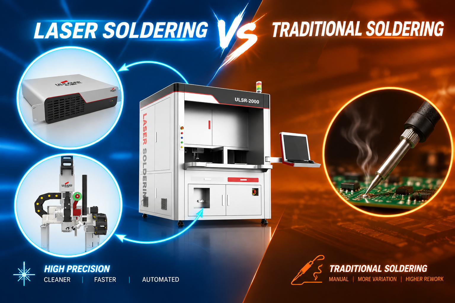
Why does laser soldering suit high-reliability aerospace electronic assemblies?
Aerospace boards are a difficult thermal compromise: high-Tg laminates and heavy copper planes need energy, while Kapton flex tails, polymer connectors, crystals and already-populated heat-sensitive devices cannot see more than a modest temperature rise. Oven reflow heats the whole mass; a laser heats a 0.3–3 mm spot.
- Localized thermal load. Adjacent components typically rise less than 20–30 °C above ambient when spot size and power are set correctly — measurable with a fine thermocouple or thermal camera during process development.
- No mechanical contact. Nothing touches the pad, which matters on 25–50 µm polyimide flex and on ceramic packages prone to micro-cracking.
- Fast, repeatable profiles. The closed-loop controller holds a setpoint (e.g. 245 °C peak for SAC305) with ±5–10 °C repeatability from joint to joint, independent of board thermal mass.
- Selective rework and mixed-technology assemblies. Leaded Sn63Pb37 (183 °C) and Pb-free SAC305 (217–220 °C) joints on the same board can each get their own recipe; space hardware still frequently specifies Sn62Pb36Ag2 for tin-whisker mitigation.
- Traceability. Every joint stores a time–temperature curve, power trace and CCD alignment image — useful evidence for first-article inspection and non-conformance review.
Note that this is soldering — solder is melted to form a metallurgical joint at 180–250 °C. Laser welding, which fuses base metal at thousands of degrees, is a different process and a different machine.
Which joint types and feed methods should you specify?
The feed method follows the joint geometry, not the other way round. A useful starting matrix for aerospace work:
| Joint / component | Feed method | Spot diameter | Laser power (typical) | Cycle time |
|---|---|---|---|---|
| Fine-pitch connector pins on flex (0.5–1.27 mm) | Solder wire 0.3–0.5 mm, or pre-tinned pad | 0.6–1.5 mm | 15–40 W | 0.5–1.5 s |
| QFN / DFN / bottom-termination devices | Solder paste jetting (Type 4–5, 20–50 µm deposit) | 0.8–2.0 mm with scan | 20–60 W | 2–6 s |
| BGA / CSP rework and CCGA attach | Solder ball placement + flux, or ball jetting | 2–4 mm (defocused) | 30–80 W | 5–20 s |
| RF / coaxial connector center pin | Solder preform or wire | 0.8–2.0 mm | 25–70 W | 1–3 s |
| Hybrid microcircuit / relay leads | Solder wire 0.25–0.4 mm | 0.5–1.0 mm | 10–30 W | 0.4–1.0 s |
Selection criteria that matter more than raw wattage: beam uniformity (top-hat preferred over Gaussian to avoid a hot center and cold rim), spot-shape control for elongated pads, nitrogen shielding at 15–25 L/min to suppress oxidation on Pb-free, and a CCD with ≥5 µm placement accuracy so the beam lands on the joint and not on the laminate.
How do you set and verify a laser soldering profile?
Start from the alloy, not the machine. For SAC305 on a Class 3 assembly, a workable window is preheat to 90–120 °C (flux activation and thermal-shock control), ramp at 100–200 °C/s, hold 25–40 °C above liquidus for 1–3 s, then controlled cool at 30–60 °C/s. For Sn63Pb37, peak at 200–215 °C. The three variables you actually tune are peak setpoint, dwell, and spot diameter — power is the dependent variable.
- Calibrate the pyrometer against a K-type thermocouple on a representative joint at least monthly; emissivity differences between shiny solder, matte pad and gold finish are the most common source of a “correct” reading that is 20–30 °C wrong.
- Use the CCD image to confirm the beam is centered; a 0.3 mm offset on a 0.5 mm pad produces asymmetric wetting and a weak fillet.
- Run a Design of Experiments on the three most critical joints, then lock the recipe and restrict operator edits to approved parameters.
- Verify with cross-section: intermetallic thickness of 1–4 µm is normal; beyond 8–10 µm signals excess energy or dwell and a brittle joint.
What acceptance checks apply to aerospace laser-soldered joints?
| Check | Method | Typical Class 3 acceptance |
|---|---|---|
| Wetting and fillet | 10–30× visual / digital microscope | Concave fillet, contact angle < 90°, no non-wetting or dewetting |
| Voiding | X-ray (2D, or CT for BGA) | Per contract; commonly ≤ 25% area on thermal/ground pads |
| Intermetallic | Cross-section, SEM | 1–4 µm continuous, no Kirkendall voids |
| Joint strength | Lead pull or shear per IPC J-STD-001 / internal spec | Minimum force per lead diameter; failure should be in the wire, not the joint |
| Adjacent-part exposure | Thermocouple or IR camera during run | Below laminate Tg and component-rated reflow limit |
| Residue / cleanliness | Ionic contamination test, visual | Per IPC-TM-650 Method 2.3.25 before conformal coat |
Coupon-level verification should precede flight hardware: at least 20–30 joints per joint family, cross-sectioned and pull-tested, with the profile data archived. Conformal-coating adhesion over laser-soldered joints should be checked early — flux chemistry and laser residue both affect wetting of the coating.
What are the common failure symptoms and how do you troubleshoot them?
- Dull, grainy, cold-looking joint. Peak temperature read low, dwell under 1 s, or a mis-calibrated pyrometer. Re-measure with a thermocouple, extend dwell in 0.2 s steps, and check for a reflective pad finish skewing the reading.
- Solder ball spatter around the joint. Ramp too fast or flux boiled off before the joint reached liquidus. Reduce ramp rate, add a 0.5–1 s preheat step at 90–110 °C, and verify paste deposit is not over-thick.
- Wicking up the lead or into the flex bend zone. Excess energy plus a long dwell lets solder follow the thermal gradient. Cut dwell, reduce spot size, and confirm the solder volume per joint.
- Discolored or blistered polyimide near the pad. Beam spill outside the joint. Reduce spot diameter, re-check CCD centering, or add an aperture/shielding gas nozzle as a physical mask.
- Non-wetting or dewetted pad. Oxidation from insufficient nitrogen coverage or expired board finish. Raise N₂ flow to 20–25 L/min, check nozzle alignment, and verify board storage and bake-out history.
- Inconsistent results across a panel. Usually fixture-related — flexure or height variation changes the effective focus. Add height sensing or a spring-loaded vacuum nest and re-verify the focal offset.
FAQ
Can laser soldering meet IPC J-STD-001 Class 3?
Yes. Class 3 is a joint-quality and process-control requirement, not a heating-method requirement. What you need is a locked recipe, calibrated temperature measurement, documented profiles per joint family, and coupon-based verification of fillet, voiding, intermetallic and strength.
Is laser soldering suitable for leaded solder in space hardware?
It is, and it is often preferred where tin-whisker mitigation calls for Sn62Pb36Ag2 or Sn63Pb37. The lower melting point actually widens the process window; the closed loop simply targets 195–215 °C instead of 245 °C.
How fast can a single joint be soldered?
Typically 0.3–3 s of beam time for a discrete joint, with 0.2–0.5 s of handling overhead. Throughput is governed by motion and vision, not by the laser.
Do I still need a reflow oven?
Usually both. Laser soldering handles the selective, heat-sensitive and rework joints; oven or vapor-phase reflow handles the dense, high-thermal-mass areas of the same assembly.
What about solder wire versus paste versus ball feeding?
Wire suits connector pins and hand-access-like geometries; paste jetting suits small bottom-termination pads with consistent volume; ball feeding suits array packages and rework. Many aerospace lines run two of the three on the same platform.
If you want to map your specific joint list and alloy set against a laser soldering configuration, send us the stack-up and we will propose a process window and verification plan.