


The easiest way to solder a wire is to stop trying to heat the wire, the pad and the solder all at once: strip 4–6 mm, tin the wire and the pad separately with a short, hot, fluxed contact, then reflow the two tinned sur…
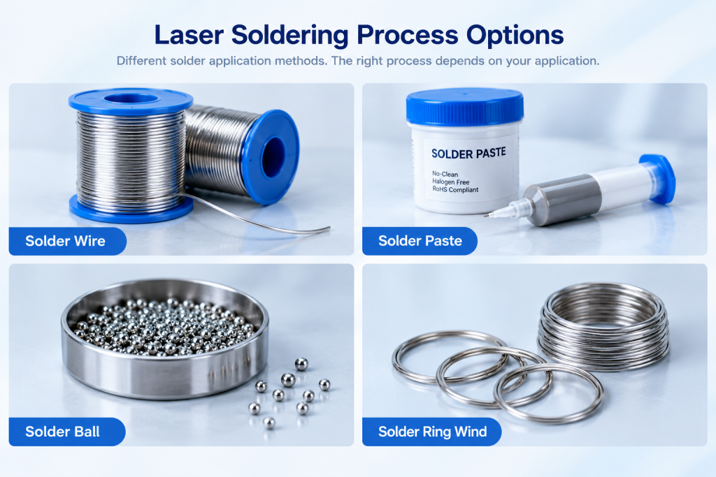
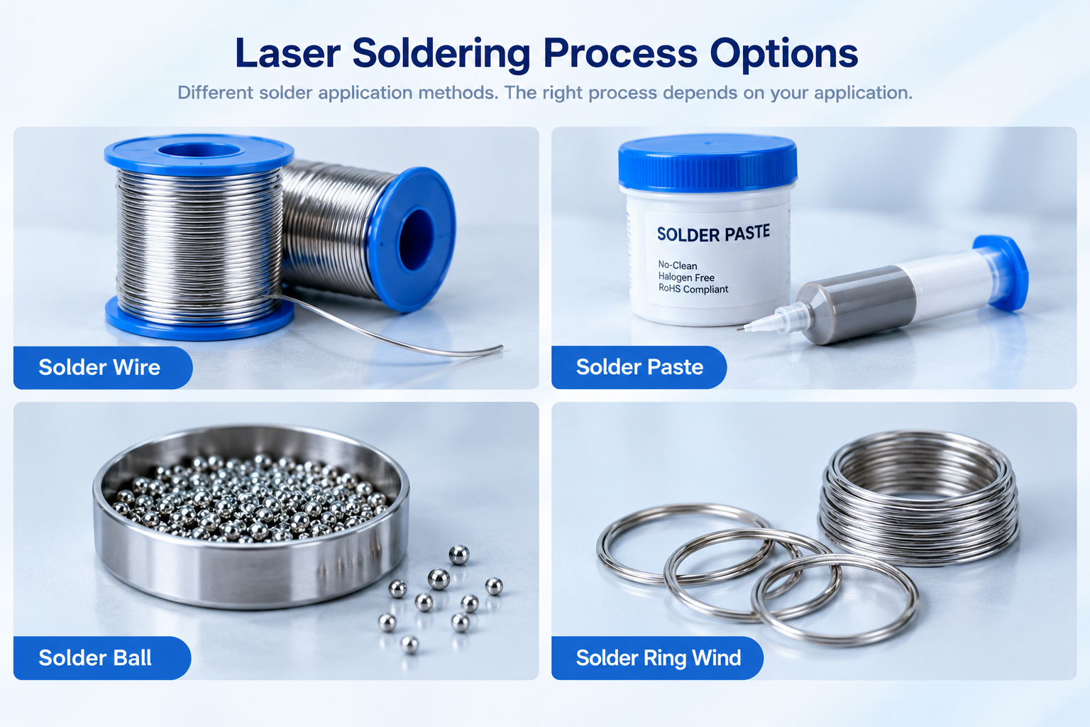
The easiest way to solder a wire is to stop trying to heat the wire, the pad and the solder all at once: strip 4–6 mm, tin the wire and the pad separately with a short, hot, fluxed contact, then reflow the two tinned surfaces together for 1–2 seconds. That three-step order removes the two things that make wire soldering hard — heat escaping down the copper strands and the joint moving while the solder is still semi-solid. In production volumes the same principle is applied with a laser as the heat source and automatic solder wire feeding, which makes the “easy” version repeatable rather than dependent on operator feel.
Why does soldering a wire feel harder than soldering a PCB pad?
Copper is an excellent heat conductor, so a 24–16 AWG stranded wire pulls heat away from the joint far faster than a 0.25 mm pad trace does. The practical consequences are predictable:
- Heat sink effect. A 60 W iron that reflows a pad in 1.5 s may need 4–5 s on a 20 AWG wire, and during those extra seconds the insulation starts to creep back.
- Oxide on strands. Stranded wire has far more exposed surface area than a pad, and the gaps between strands trap oxide and air. Solder will not wet what flux has not cleaned.
- Movement during solidification. A wire is mechanically free until it is clamped. Any vibration in the 217 °C → 200 °C window produces a dull, grainy, low-strength joint.
- Wicking under insulation. Once the strands reach reflow temperature, capillary action pulls solder back toward the insulation, stiffening the wire and creating a stress riser.
The fix for all four is the same: get the joint to temperature fast, keep the heated zone short, and hold the wire still.
The easy manual method: tin, flux, reflow, hold
For prototype and rework work this sequence is the fastest reliable route for a wire-to-pad or wire-to-terminal joint with Sn96.5Ag3Cu0.5 (SAC305, 217–220 °C melting) or Sn63Pb37 where leaded process is permitted.
- Strip: 4–6 mm for 24–16 AWG. Do not nick the strands — a nick becomes a crack initiation point under vibration.
- Flux: apply a no-clean ROL0 liquid flux to the strands and to the pad. If your solder wire has a 2–3 % rosin core this is often enough on the pad, but pre-fluxing the strands is what makes the difference.
- Tin the wire: iron tip at 350 ± 10 °C, generous tip-to-wire contact, feed 0.6–0.8 mm solder wire into the joint (not onto the tip), 1–2 s. Stop while the strands are still visible as a contour — a smooth, flooded blob means you overheated it.
- Tin the pad: same tip, 0.5–1 s, thin film only.
- Reflow together: place the tinned wire on the tinned pad, touch the iron to the wire for 1–1.5 s until the solder on both surfaces merges, remove the iron, and hold the wire motionless for 2 s.
- Clamp or heat-sink: a small aluminium clamp 3–4 mm behind the strip line keeps wicking short. Slide heat-shrink on before you solder, not after.
Manual iron vs. laser soldering with wire feeding for wire joints
When the joint count per shift goes up, the “easy” method stops being easy because the heat dose is set by the operator’s hand. A laser source delivers a defined energy dose to a defined spot, and a motorised solder wire feeder delivers a defined volume at a defined time. Comparison for typical automotive sensor and connector wire joints:
| Parameter | Manual iron | Laser soldering + wire feed |
|---|---|---|
| Heat source | Conduction, 330–370 °C tip | Diode 915/980 nm or fiber 1070 nm, 30–120 W |
| Spot / heated area | Tip face, 1–2 mm | 1.5–3 mm focused spot |
| Joint cycle time | 3–6 s including hand motion | 1–3 s, position-to-position |
| Solder wire | 0.6–0.8 mm, hand-fed | 0.5–1.0 mm, feeder-controlled volume |
| Temperature control | Tip setpoint only | Closed-loop pyrometer feedback on the joint, 20–50 ms sampling |
| Positioning | Operator eye | CCD vision alignment, ±0.05 mm typical |
| Atmosphere | Rosin core | Optional N₂, 15–25 L/min at the nozzle |
| Verification | Visual, post-shift | In-line AOI, per-joint |
The important point is not that laser is “better”; it is that the three variables that make wire soldering unpredictable — time at temperature, solder volume, and part position — become programmed values instead of operator judgement. For a 0.35 mm² automotive wire onto a connector terminal, a typical recipe is a 2.0 mm spot, 60–90 W with a 150–250 ms ramp, 0.8–1.2 s at reflow, wire feed of 3–6 mm at 20–40 mm/s, and pyrometer hold at 240–255 °C measured at the joint.
Symptoms, causes and fixes for wire solder joints
| Symptom | Likely cause | Corrective action |
|---|---|---|
| Dull, grainy surface; solder balls up | Wire moved during solidification | Add a clamp; extend hold time by 1–2 s; reduce wire feed to shorten the mushy stage |
| Solder will not wet the strands | Oxide or contamination; insufficient flux; plated strand (nickel/aluminium) | Re-strip, re-flux, shorten time between strip and solder; confirm strand metallurgy before attempting |
| Insulation shrunk back or melted | Excess dwell or heat conducted down the strands | Shorten strip to 4 mm, add heat sink, reduce tip contact to <2 s, or move to localized laser heating |
| Solder wicked 3–5 mm under insulation | Overheating, over-feeding, no clamp | Clamp 3 mm behind strip line; reduce feed volume; cap joint temperature |
| Strands separated after pull test | Cold joint — solder never fully reflowed onto copper | Raise joint temperature 15–20 °C, extend reflow 0.3 s, verify with cross-section |
| Icicles or spikes | Iron or laser removed before reflow completed; too much solder | Reduce feed volume ~20 %, extend dwell slightly, slow the withdrawal |
What does a good wire joint look like at acceptance?
Judge the joint against IPC-A-610 / J-STD-001 style criteria rather than “it looks shiny”:
- Wetting: solder feathers onto the copper and the terminal with a contact angle under 90°; no gaps between solder and strand.
- Strand contour: individual strand outlines remain visible through the solder — this is the single best indicator that you did not overheat.
- Wicking limit: solder stops at least 1–2 mm short of the insulation, and never enters the flexible strand zone.
- Fillet: concave, continuous around the wire; no voids, no blowholes, no flux residue bridging conductors.
- Mechanical check: a pull test at the drawing-specified force (commonly 10–30 N for signal wires) with strand break outside the joint rather than pull-out.
FAQ
Can I solder a wire without flux?
Only if the solder wire has an active rosin core and the copper is freshly stripped and clean. For stranded wire, adding liquid flux to the strands before tinning measurably shortens wetting time and is the difference between a 1.5 s and a 4 s joint.
What temperature should I use to solder a wire?
For SAC305, a tip at 350 ± 10 °C with 1–2 s contact, or a joint temperature of 240–255 °C measured at the wire. Leaded Sn63Pb37 reflows at 183 °C and is typically run at a 320–340 °C tip. Higher tip temperatures do not make the joint easier — they melt insulation faster.
Why won’t solder stick to my wire?
In order of frequency: oxide from a wire stripped hours ago, insufficient flux, a nickel- or aluminium-based conductor that needs a different process entirely, or a tip that has lost its plating and no longer transfers heat. Re-strip, re-flux, and check tip condition before changing any parameters.
Can laser soldering handle wire-to-connector joints in volume?
Yes, and this is one of the main uses in automotive sensor and connector assembly. The wire is presented by a fixture or gripper, CCD alignment locates the terminal, the laser heats the joint under pyrometer feedback while the wire feeder advances a set length, and AOI verifies fillet and wicking before the part leaves the station.
How do I stop solder from wicking under the insulation?
Three levers, in order of effectiveness: clamp the wire 3 mm behind the strip line, reduce the solder feed volume so there is less excess to wick, and shorten the time above liquidus. If wicking persists on fine stranded wire, the joint is simply receiving more heat than it needs.
If you are weighing manual wire soldering against an automated laser platform for a specific wire gauge, terminal and takt time, send us the joint drawing and we will tell you which process window fits.