


Before laser soldering medical device electronics, a CCD vision alignment check confirms three things at every joint: the correct fiducials are found and the board datum is established, the part and pad sit within X‑Y‑th…
Before laser soldering medical device electronics, a CCD vision alignment check confirms three things at every joint: the correct fiducials are found and the board datum is established, the part and pad sit within X‑Y‑theta tolerance of the programmed position, and the laser spot’s real position matches the coordinates the camera reported. In practice this is a pre‑solder routine covering fiducial recognition, part position, Z focus height and the camera‑to‑laser offset — typically held to ±10 µm for pitches of 0.4 mm and below, and ±25 µm for larger pads. Skipping or shortcutting this check is the most common reason a well‑tuned laser soldering recipe suddenly produces cold joints on a validated line.
Why does vision alignment carry more weight on medical device electronics?
Medical electronics tend to be small, dense and low‑volume/high‑mix: sensor leads on flex, 0.3–0.4 mm pitch connector tails, hermetic package feedthroughs, fine wire terminations on rigid‑flex. Three factors raise the cost of misalignment:
- Small energy margin. A 0.4 mm solder ball or a 0.25 mm paste dot delivers a fixed amount of energy. A 50 µm lateral offset can put 20–30% of the beam onto solder mask or the component body instead of the pad, producing partial wetting or local pad/laminate damage rather than an obvious miss.
- Low rework tolerance. Repeated localized heating on thin flex or on a populated sensor assembly risks delamination and adjacent‑joint reflow, so a defect found after soldering is far more expensive than a pre‑solder alignment reject.
- Validated process expectation. Under ISO 13485 and 21 CFR 820 expectations, the alignment step needs documented evidence — measurement system capability, calibration records and per‑unit traceability — not just an operator’s judgement that the crosshair looks centred.
What should a pre-solder CCD alignment check actually verify?
A useful check is a sequence, not a single image grab. On ULiLASER inline laser soldering platforms the pre‑solder sequence typically runs:
- Board datum and fiducials. Two or three fiducials, 0.5–1.0 mm circles or crosses, with a grey‑level contrast gate (a delta of roughly 40 levels or more) so glossy solder mask or gold finish cannot be mistaken for a mark.
- Part presence and orientation. Pin‑1 or polarity mark confirmed, plus a basic body‑outline check to catch a reversed or shifted component before any energy is delivered.
- Joint position in X‑Y. Pad centroid versus the programmed solder delivery point — for ball feeding this is the nozzle drop point, for paste it is the deposit centroid, for wire it is the contact point.
- Theta. Rotational error typically held to ±0.05°–±0.10°; critical on multi‑pin connectors where a small rotation becomes a large error at the end pin.
- Z and focus. Standoff or seating height confirmed by a laser displacement sensor or the vision focus metric, so the beam is delivered at the correct defocus plane rather than at a nominal height.
- Camera‑to‑laser offset. The beam is aimed by the galvo or the motion stage using camera coordinates, so the optical axis‑to‑beam offset must be re‑verified after any optical or nozzle change.
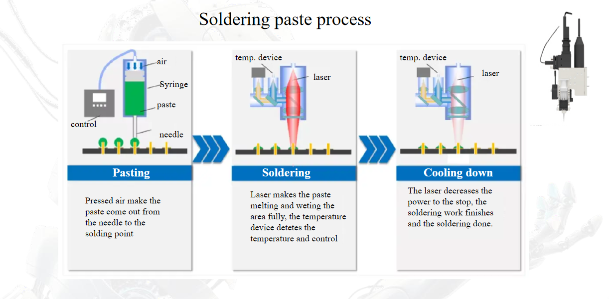
- Deposit confirmation. Where paste or a ball is placed before lasing, a 2D area/centroid check plus a height reading catches a short shot or a squashed ball before it becomes a cold joint.
Which camera, lens and illumination settings give repeatable micron-level alignment?
Resolution alone does not buy accuracy; distortion, illumination stability and depth of field usually matter more. A practical starting point for medical assemblies:
| Parameter | Typical setting | Why it matters | Verification |
|---|---|---|---|
| Field of view | 4–15 mm, covering at least two fiducials per shot | Local fiducials correct for board‑level distortion on flex | Confirm edge fiducials stay in frame across the panel |
| Pixel resolution | 3–8 µm/pixel | At least 3–5 pixels across the feature being measured | Measure a certified grid target |
| Lens | Telecentric, distortion under ~0.1% | Non‑telecentric lenses report position differently at different heights | Check the same target at two Z heights |
| Depth of field | ±0.15–0.30 mm | Flex and connector overhang vary in height | Measure edge sharpness across the joint area |
| Illumination | Coaxial plus segmented ring; blue (~470 nm) for gold/ENIG, red (~630 nm) for matte finishes | Reduces specular glare that causes fiducial false rejects | Test on bare, pasted and populated boards |
| Alignment tolerance | ±10 µm (≤0.4 mm pitch); ±25 µm (≥0.5 mm) | Sets the reject gate and the capability target | Gage R&R under 10% of tolerance |
| Theta accuracy | ±0.05°–±0.10° | End‑pin error on long connectors | Rotate a target by known angles |
How do you calibrate and prove alignment is still correct in production?
Alignment drifts for mundane reasons: thermal growth of the frame after cold start, a nozzle change that shifts the pick point, a lens that picked up flux aerosol, or a filter change that altered illumination intensity. A workable routine:
- Warm‑up first. Let the machine run 20–30 minutes before the first alignment verification; check for offset drift between cold and warm state and record it.
- Verify the camera‑to‑laser offset on a consumable target — thermal paper or ablative tape at the working height — and compare the mark centroid with the camera crosshair. Accept only if the residual is inside your stated tolerance, typically ±15 µm.
- Run a capability study, not a spot check. Ten boards, three operators, three trials, with Gage R&R reported as a percentage of the alignment tolerance. Anything above 10% means the measurement, not the process, is the limiting factor.
- Re‑verify at defined triggers: shift start, nozzle or feeder change, optics cleaning, laser module service, product changeover, and every 4–8 hours on continuous runs.
- Log every result with board ID, offsets, fiducial scores and operator, so the alignment record sits alongside the temperature profile and AOI result for the device history record.
What do misalignment symptoms look like, and how do you troubleshoot them?
- Consistent one‑direction offset on every joint. Camera‑to‑laser offset has drifted, or a stale fiducial template is being reused. Re‑run beam calibration and re‑teach the fiducial; do not compensate by editing the program coordinates.
- Good first article, worsening offset over a shift. Thermal growth or a loosening camera mount. Let the machine reach thermal equilibrium, then re‑check; if drift repeats, inspect the mount and re‑calibrate.
- Frequent fiducial false rejects on gold or ENIG boards. Specular glare saturating the sensor. Reduce exposure, switch illumination wavelength, or move to a cross‑shaped fiducial with a matte surround.
- Vision passes but the ball lands beside the pad. Nozzle pick‑position offset or worn nozzle tip, not a camera fault. Recalibrate the pick point and check tip concentricity.
- Intermittent theta errors on flex. Poor seating or warpage. Add support pins or vacuum hold‑down and confirm the height map before alignment.
- Alignment nominal but wetting incomplete. The problem is downstream of vision — check delivered energy, spot size and the pyrometer trace rather than chasing the camera.
FAQ
How often should CCD alignment be checked before laser soldering?
At every shift start, after any nozzle, feeder or optics change, at product changeover, and every 4–8 hours during continuous production. Verify the camera‑to‑laser offset on a consumable target, not just the fiducial image.
What alignment accuracy is realistic for 0.3 mm pitch connectors?
Around ±10 µm at the joint with a telecentric lens and a capable Gage R&R. Beyond roughly ±15 µm, end‑pin offset and partial wetting begin to appear on the outermost leads.
Can the same camera also check the solder ball or paste deposit?
Yes — a 2D area and centroid check catches short shots and displaced deposits. Add a height sensor if you need volume or squash data, since a 2D image cannot confirm deposit thickness.
Is a vision alignment check enough evidence for a validated medical process?
It is one element. Pair it with a measurement system study, calibration records, defined re‑verification triggers and per‑unit traceability so the alignment data can be audited as part of installation and process qualification.
Does the beam need re‑alignment whenever a nozzle changes?
The pick/place nozzle offset yes, since ball placement position changes; the camera‑to‑laser beam offset only if optics, the galvo or the laser module itself has been disturbed.
If you are specifying an inline laser soldering cell for a medical device program, our application team at ULiLASER can review your pad geometry, alignment budget and inspection requirements with you.