



Post-solder AOI inspects laser solder joints by capturing high-resolution 2D and 3D images immediately after the joint solidifies, then comparing fillet geometry, solder volume, position and surface quality against a qua…
Post-solder AOI inspects laser solder joints by capturing high-resolution 2D and 3D images immediately after the joint solidifies, then comparing fillet geometry, solder volume, position and surface quality against a qualified reference — normally inline and inside the same cell cycle, at roughly 5–20 µm/pixel depending on joint size. Because laser soldering creates a small heat-affected zone, a fast 50–500 ms reflow and darker flux residue than oven reflow, a standard SMT AOI library will over-call and under-call on these joints. The inspection recipe has to be built from laser-specific reference joints and validated against cross-sections before it is trusted.
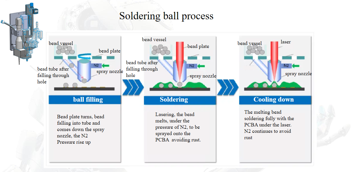
What defects can post-solder AOI actually catch on a laser solder joint?
AOI is a surface-and-geometry tool. It is strong on shape and volume proxies, weak on anything happening inside the joint. The table below reflects what we see on inline cells running laser wire, paste and ball feeding.
| Defect | AOI capability | Detection method | Process note |
|---|---|---|---|
| Insufficient solder / short fillet | Yes | 3D fillet height + low-angle 2D | Usually wire-feed starvation or power droop |
| Bridging between pads | Yes | 2D, top and low-angle | Reliable at ≥ 0.2 mm gap |
| Solder spatter / micro-balls | Yes, ≥ 50 µm | 2D dark-field + height check | Must be separated from flat flux splatter |
| Component offset / tombstone | Yes | 2D fiducial-referenced | Common after fast laser reflow of small parts |
| Cold / non-wetted joint | Marginal | Low-angle specular + texture metric, correlated with thermal log | AOI alone is unreliable; treat as a screening flag |
| Charred / burnt flux | Yes, with colour channel | Diffuse RGB, narrow hue band | Easily confused with dark residue |
| Internal voiding | No | X-ray or CT required | Surface pitting is not a void indicator |
| Micro-cracks in the joint | No | X-ray/CT or cross-section | Below optical resolution and contrast limits |
The marginal row matters most. A laser joint that never wetted shows a convex, mirror-like bead with a wetting angle above 90°, and it scatters low-angle light differently from a properly concave fillet. That difference is detectable, but only with a specular-reflection metric and a tight illumination setup — and it should be cross-checked against the per-joint thermal log before you scrap a board.
Why do laser solder joints need their own AOI recipe instead of a reflow library?
Four physical differences drive most false calls:
- Fillet shape. Localised heating produces narrower, more concave fillets, typically with wetting angles of 15–40°. Thresholds copied from oven reflow (often 45–60°) will call good joints “insufficient”.
- Residue. The short thermal cycle burns off less flux, so more amber or brown residue remains near the joint. It reads as contamination or charring unless the colour classifier is narrowed.
- Surface finish. Laser joints are often near-mirror. At normal incidence the sensor saturates and the fillet edge disappears; off-axis or polarised illumination is required.
- Ball-jetting signature. Where solder balls are jetted, the ball top carries a small crown or dimple from solidification. The reference model must accept it as nominal.
Practical rule: build the reference model from 30–50 confirmed-good joints per joint type, collected across at least three boards from different lots — not from CAD nominal dimensions, which never match the real fillet.
Which camera and lighting setup do you need for joints this small?
| Joint / feature size | Pixel resolution | Camera | Illumination | 3D needed? |
|---|---|---|---|---|
| ≥ 0.5 mm (connector pins, wire terminals) | 15–25 µm | 5 MP | Segmented RGB ring + low-angle ring | Optional |
| 0.2–0.5 mm (0402/0201, fine-pitch leads) | 8–15 µm | 12–20 MP | Multi-angle + coaxial | Yes, for fillet height |
| < 0.2 mm (ball jetting, 0.3 mm pitch, die attach) | 3–8 µm | 20 MP with telecentric lens | Dome diffuse + low-angle + coaxial | Yes |
Two specifications worth writing into the purchase order: height repeatability of ±1–3 µm on the 3D channel, and a telecentric objective if joints sit near board edges or tall components, since perspective error otherwise shifts measured fillet height by several percent. Low-angle illumination should be adjustable between roughly 10° and 30° — 10° reads wetting angle on shallow fillets, 30° reads lead-tip coverage on taller ones.
How do you set acceptance thresholds and qualify the AOI program?
Start from the drawing and IPC-A-610 Class 2 or 3, then tighten only where the process is capable. Typical starting points for laser joints:
| Parameter | Typical setting | Measurement |
|---|---|---|
| Fillet height | ≥ 25% of joint height, per drawing | 3D height map |
| Wetting angle | ≤ 90°; good joints usually 15–40° | 3D slope fit |
| Ball diameter | Nominal ±10% | 2D area + 3D height |
| Component offset | ≤ 25% of pad width | Fiducial-referenced 2D |
| Spatter | No sphere > 0.1 mm within 0.5 mm of joint | 2D shape + height |
| Void area (if specified) | Commonly ≤ 25% on thermal pads — verify against your drawing | X-ray, not AOI |
Qualification: seed at least 30 defects per defect type across the panel, run three operators × three runs on the same image set, and require attribute agreement (kappa) ≥ 0.75 before release. Targets we work to are a false-call rate below 500 ppm and zero escapes on seeded defects. Re-validate whenever the solder wire or paste lot, nozzle, or laser recipe changes — all three shift the visual signature.
Where does AOI sit in an inline laser soldering cell, and how does it close the loop?
- Position. Immediately after the joint solidifies and before unload; allow 100–300 ms for surface reflection to stabilise, otherwise measurement scatter doubles.
- Cycle time. Field capture is typically 0.3–2 s; multi-field stitching keeps up with cells running 0.5–3 s per joint.
- Feedback. Send the per-joint defect code and measured fillet height back to the laser controller. Adjust power or pulse duration only when an SPC rule trips (for example, seven consecutive joints trending low), within ±5% power and ±10% time limits — never per unit, or you will chase measurement noise.
- Traceability. Log images and measurements per serial number so a field return can be traced to a specific joint and thermal profile.
Troubleshooting: false calls and escapes
- Good joints called “insufficient solder”. Check for a tall neighbour shadowing the low-angle ring, then for specular saturation. Lower gain, add a crossed polariser, and base the pass/fail on the 3D height channel rather than 2D area.
- Clean joints flagged as burnt. Flux residue is being read as charring. Narrow the hue band, add a UV channel, and re-teach from a verified-clean sample.
- Flux splatter counted as solder balls. Classify on circularity plus height — solder spheres sit proud of the surface, flux splatter is flat.
- Cold joint escaped. The program is 2D-only. Add the low-angle specular metric and review the thermal log for joints that peaked below the paste or wire melting window.
- Program drifts after a fixture change. Re-run fiducial and Z calibration, then confirm with a golden board — daily golden-board verification catches most drift before it reaches production.
FAQ
Can AOI detect voids inside a laser solder joint?
No. Voids are internal and invisible to optical inspection. Use X-ray or CT; AOI can only flag surface pitting, which does not correlate reliably with void content.
What pixel resolution do I need for 0.3 mm pitch laser solder joints?
Plan on 5–10 µm/pixel with a telecentric lens. Coarser than 10 µm/pixel, fillet edges blur and height measurement repeatability falls off quickly.
How many good joints are needed to build a reliable reference model?
30–50 confirmed-good joints per joint type, taken from at least three boards across different lots, and verified by cross-section on a sample of five.
Why does my AOI reject joints that pass cross-section?
Almost always a recipe built on oven-reflow appearance: wetting-angle thresholds too wide, colour classifier too loose, or specular saturation at the fillet edge. Rebuild the model from laser-specific references and re-check the illumination angle.
Is AOI alone enough for final quality release?
For geometry, position and spatter, yes. Pair it with X-ray for voiding on thermally critical joints and a periodic cross-section audit to keep the AOI thresholds honest.
If you are specifying an inline laser soldering cell and need AOI thresholds, optics and feedback logic matched to your joint sizes, send us your board details and we will map out a workable inspection configuration.