


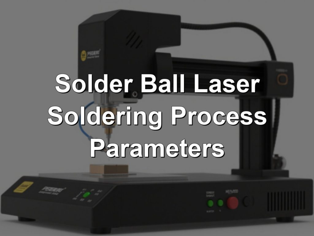
Solder ball laser soldering process parameters come down to five linked variables: laser power (or better, energy density at the joint), spot diameter, heating and hold time, peak temperature with time above liquidus, an…
Solder ball laser soldering process parameters come down to five linked variables: laser power (or better, energy density at the joint), spot diameter, heating and hold time, peak temperature with time above liquidus, and the atmosphere/flux around the ball. Get the energy density right and the joint forms in under two seconds; miss it and you get either a cold, grainy ball or a burnt flux ring with a brittle intermetallic layer. The numbers below are practical starting points for SAC305 and similar lead-free alloys, and every recipe should be confirmed on your own pads, board thickness and component thermal mass before release to production.
Which Parameters Actually Define a Solder Ball Laser Soldering Recipe?
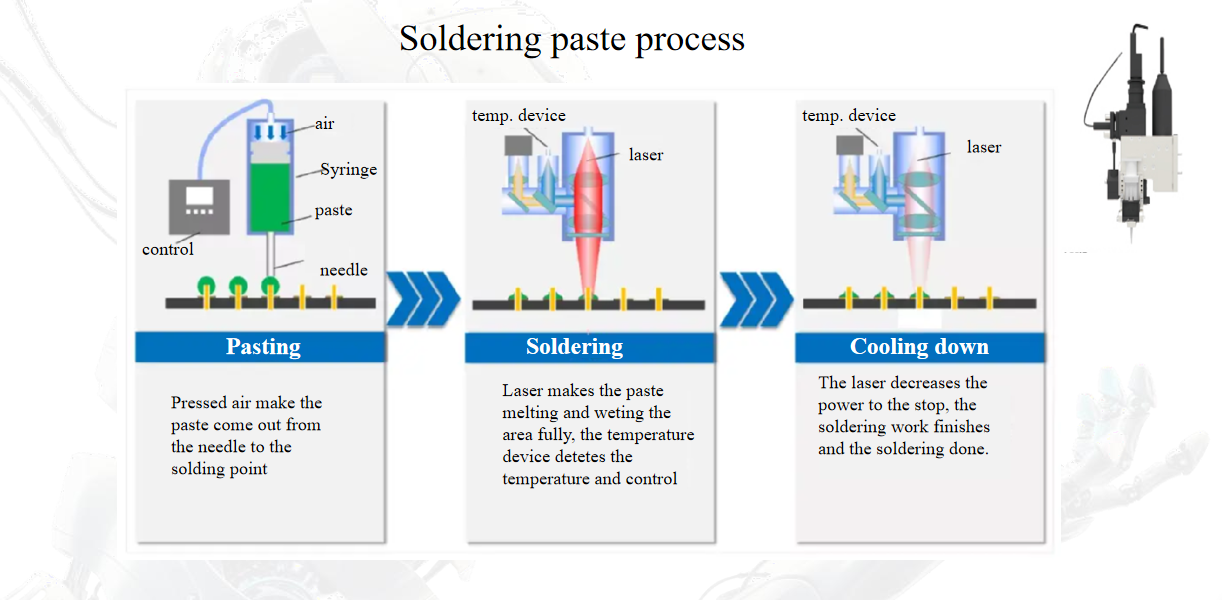
A repeatable recipe is a temperature profile, not a single power number. The laser is only the heat delivery mechanism; the closed-loop pyrometer and the dwell time decide whether the ball and the pad interface both reach reflow. Set these parameters in this order:
- Ball diameter and alloy — 0.20–1.00 mm for most connector, sensor and package applications; SAC305 (liquidus 217 °C) and low-temperature SnBi or SnAgCu variants behave very differently at the same energy.
- Spot diameter — typically 1.0–1.8× the ball diameter, large enough to heat the pad annulus evenly, small enough to avoid heating adjacent parts.
- Laser power and modulation — peak power sets the ramp; the controller then modulates down to hold peak temperature.
- Ramp rate, peak temperature, time above liquidus (TAL), cooling rate.
- Flux deposit and atmosphere — flux volume and nitrogen purity determine wetting and spatter, independent of the laser.
| Parameter | Typical range (SAC305) | What it controls |
|---|---|---|
| Ramp rate | 100–400 °C/s | Spatter, flux activation, thermal shock to nearby parts |
| Peak temperature | 240–260 °C (liquidus +25 to +45 °C) | Full fusion, wetting, IMC growth |
| Time above liquidus | 0.3–1.5 s | Void escape, fillet formation, IMC thickness |
| Cooling rate | 50–150 °C/s | Grain structure, IMC thickness, joint ductility |
| Total cycle per joint | 0.8–3 s | Throughput and thermal load on the substrate |
| Nitrogen purity / O₂ | 99.99% N₂, O₂ < 1000 ppm (often < 100 ppm) | Wetting angle, oxide re-formation, dross on the ball |
| Placement accuracy (CCD) | ±30 µm typical, vision alignment ±10 µm | Ball centring, self-alignment capability, offset defects |
How Do You Set Laser Power and Heating Time for Different Ball Diameters?
Energy scales with ball volume, so a 0.6 mm ball needs roughly 3.4× the energy of a 0.4 mm ball (volume ratio 3.375) plus extra to heat the pad. In practice you scale power and time together rather than pushing power alone, because a very high peak power over a short time overheats the flux and the pad surface before heat conducts into the ball. The table below is a working starting matrix for SAC305 on OSP or ENIG pads; treat the power figures as peak values that the closed-loop control will modulate down during the hold phase.
| Ball diameter | Peak laser power | Spot diameter | Heating + hold time | Notes |
|---|---|---|---|---|
| 0.20–0.25 mm | 8–20 W | 0.3–0.5 mm | 0.3–0.6 s | Small thermal mass; risk of pad scorch, keep peak ≤255 °C |
| 0.30–0.40 mm | 15–35 W | 0.5–0.8 mm | 0.5–1.0 s | Most common connector/sensor range |
| 0.50–0.60 mm | 30–60 W | 0.8–1.2 mm | 0.8–1.5 s | Add a short preheat step at 120–150 °C to control spatter |
| 0.76–1.00 mm | 50–100 W | 1.2–1.8 mm | 1.2–2.5 s | Check substrate warpage; consider two-stage profile |
Two corrections are usually needed after the first trial. If the joint wets but the ball stays visibly spherical with a narrow contact angle, the energy reached the ball surface but not the pad interface — increase hold time rather than peak power so the interface catches up. If the ball collapses and spreads across the solder mask, the energy is too high for the pad area; reduce peak power by 10–15% and shorten TAL.
Why Does Closed-Loop Temperature Control Matter More Than the Power Setting?
Laser soldering is fast enough that open-loop timing is unreliable: pad finish, copper thickness, board mass and component heat-sinking all shift the actual joint temperature by tens of degrees at the same power. A pyrometer sampling at around 1 kHz, feeding a PID loop that modulates laser output, keeps the joint on the profile regardless of those variations. Three practical points when commissioning the loop:
- Emissivity and spot targeting. Aim the pyrometer spot at the ball/pad interface, not the surrounding mask, and set emissivity against a thermocouple-verified trial. A misaimed sensor produces a profile that looks perfect on screen and cold joints on the board.
- Verify with a real profile, not the display. Attach a fine thermocouple or use a test coupon with a profiler at least once per recipe and after any hardware change; confirm peak and TAL against the recipe, not just the setpoint.
- Cap the peak in software. A hard limit at 260–270 °C protects temperature-sensitive components (connectors, sensors, LED packages) if a ball is misplaced or missing and the loop chases an unheated target.
Which Supporting Parameters Cause Most Solder Ball Laser Soldering Defects?
Most failures that look like “laser parameter” problems are actually flux, atmosphere or placement issues. Use this symptom-to-action list before you touch the profile:
- Dull, grainy, incompletely fused ball: peak temperature low or TAL under 0.3 s; check pyrometer calibration and raise peak by 10 °C, extend TAL by 0.2 s.
- Solder spatter and micro-balls around the joint: ramp too fast or flux outgassing violently; add a 100–150 °C preheat step of 0.2–0.4 s, reduce flux volume, verify flux shelf life and storage.
- Ball offset or rolled off the pad: placement accuracy, insufficient flux tack, or excessive nitrogen flow blowing the ball before reflow; reduce gas flow and re-check nozzle-to-board standoff.
- Voids visible on X-ray: volatiles trapped under the ball or oxidised pad; extend TAL slightly, improve N₂ coverage, confirm pad cleanliness and OSP integrity.
- Discoloured mask or delamination near the joint: spot too large or peak too high; shrink spot to ≤1.5× ball diameter and cap peak temperature.
- Brittle joint or excessive intermetallic: too much time above liquidus; cut TAL by 30–50% and increase cooling rate with directed N₂ or air.
Acceptance checks worth writing into the work instruction: cross-section IMC thickness in the 1–4 µm range, void area below 10% for signal joints (relaxed for power joints per application), visible fillet on at least two sides, wetting angle under 40°, and shear or pull strength within the batch baseline established during qualification.
FAQ
What peak temperature should I start with for a 0.4 mm SAC305 solder ball?
Start at 245–250 °C, roughly 30 °C above the 217 °C liquidus, with 0.5–0.8 s above liquidus. Confirm with a thermocouple profile on a real board, then adjust ±10 °C based on wetting and void results.
How long does one laser solder ball joint take?
Typical heating and hold is 0.3–1.5 s depending on ball size and board thermal mass; with ball placement, vision alignment and AOI, effective throughput is usually governed by the handling and inspection modules rather than the laser dwell.
Is nitrogen mandatory for solder ball laser soldering?
Not always, but it widens the process window considerably. With O₂ below 1000 ppm, wetting improves and spatter drops; with good flux and clean ENIG pads some applications run in air, at the cost of a narrower peak-temperature window.
Can I use the same recipe for different pad finishes or ball sizes?
No. OSP, ENIG and tin-plated pads absorb and wet differently, and energy scales with ball volume. Re-qualify the profile whenever ball diameter, alloy, pad finish or board thickness changes, and keep the recipe revision tied to the part number.
How do I know the recipe is stable in production?
Track peak temperature and TAL logs from the closed-loop controller per joint, plus a daily first-article cross-section and X-ray void check. A drift of more than 10 °C in logged peak temperature usually points to window contamination, a degraded pyrometer lens or a flux lot change before it shows up as a defect.
If you are defining a recipe for a specific ball size, pad finish and component mix, send us the details and we can help you set the initial profile and acceptance criteria.