


An inline laser soldering module integration means mounting a laser soldering head — solder ball, paste or wire feeder, CCD vision alignment, closed-loop temperature control and post-solder AOI — directly into an existin…
An inline laser soldering module integration means mounting a laser soldering head — solder ball, paste or wire feeder, CCD vision alignment, closed-loop temperature control and post-solder AOI — directly into an existing SMT conveyor line so boards are soldered at line takt with no manual loading. In practice the job splits roughly 30% mechanical and electrical work (SMEMA handshake, conveyor height and width, clamping, nitrogen, exhaust, MES link) and 70% process qualification (fiducial alignment, thermal profile, repeatability, IPC-A-610 acceptance). Get the interface dimensions and the thermal window right up front and the module behaves like any other inline station; skip either and you inherit intermittent cold joints that are hard to trace later.
What does an inline laser soldering module integration actually include?
A production-ready module is more than a laser source on a gantry. A typical configuration for connector, THT and heat-sensitive SMT joints includes:
- Laser head and delivery: diode laser at 808–980 nm, fiber-coupled or direct, 30–120 W at the workpiece for spot diameters of 0.3–3.0 mm; pyrometer or thermopile feedback sampled at 1–10 kHz closing the loop on measured joint temperature rather than open-loop power.
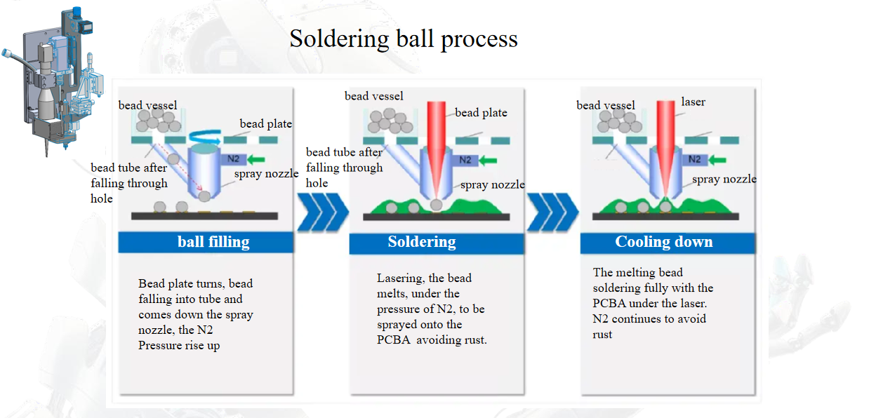
- Solder feeding: ball feeder (0.2–0.76 mm spheres), paste dispenser (Type 4–6), or wire feeder (0.3–0.8 mm) with feed-verify sensors, since a missed ball is the single most common cause of a false “no-reflow” alarm.
- Vision: 2–5 MP CCD with telecentric lens, fiducial alignment typically ±25–50 µm, plus post-solder AOI for fillet presence, wetting angle and bridging.
- Board handling: SMEMA-compatible conveyor, 900 ± 20 mm transfer height, motorised width adjustment (50–350 mm), vacuum or pin clamping with Z-lift, and an upstream/downstream buffer of 1–2 boards.
- Utilities and services: 200–240 VAC single phase, 3–6 kW; dry compressed air at 5–6 bar; nitrogen 99.99% at 5–25 L/min per head; fume extraction at the nozzle; light curtain and door interlock around the enclosure.
- Data link: SECS/GEM or TCP/IP to the line MES, with per-joint logs of peak temperature, time above liquidus and laser energy — this is what makes traceability audits survivable.
How do you match the module’s conveyor and footprint to an existing SMT line?
Mechanical mismatch is the cost-effective failure to prevent and the most expensive to discover during ramp. Confirm these values against your line drawing before the purchase order, not after the rigging crew arrives:
| Interface item | Typical module spec | What to verify on your line |
|---|---|---|
| Conveyor height | 900 ± 20 mm | Measured height at the splice point, not the datasheet value; check after levelling |
| Board width range | 50–350 mm | Widest and narrowest assemblies in the product mix, including carriers and pallets |
| Edge clearance | 3–5 mm belt overhang | Component keep-out within 5 mm of board edge; bottom-side hardware |
| Module length | 1.2–2.0 m including buffers | Floor space plus service access of 600–800 mm on the operator side |
| Takt / cycle | 0.8–3 s per joint; 2–6 joints per board | Whether the module becomes the line bottleneck; consider dual-lane or two heads |
| Communication | SMEMA + SECS/GEM | Upstream/downstream handshake timing, board-present sensor logic |
Two practical checks: run a board-transfer trial with your thinnest (0.6 mm) and thickest (2.4 mm) assemblies to confirm the clamp does not bow the PCB — a 0.1 mm bow across a connector row shifts focal height enough to unbalance heating. Second, confirm the takt with the feeder in the loop, because ball pick-and-place time, not laser heating time, usually sets the real cycle.
Which process parameters must be fixed before the module goes inline?
Lock the window on coupons and first-article boards, then write it into the recipe with tolerances. The table below reflects common SAC305 work; adjust for Sn63Pb37 (183 °C eutectic) or high-temperature alloys.
| Parameter | Starting window | Notes |
|---|---|---|
| Spot diameter | 1.0–1.5 × joint diagonal | Too small scorches the pad edge; too large heats neighbouring parts |
| Peak joint temperature | 235–250 °C (SAC305) | 20–35 °C above liquidus; measure with a K-type on the actual joint, not the board surface |
| Time above liquidus | 0.5–3.0 s | Laser heating is fast; long TAL drives intermetallic growth and flux burn-off |
| Ramp rate | 50–150 °C/s | Fast ramp is the point of the process; splatter usually means flux outgassing, not ramp |
| Cooling rate | 30–100 °C/s | Natural in still air; forced air can shift adjacent joints |
| Nitrogen flow / O₂ | 5–25 L/min; < 1000 ppm O₂ at the joint | Below 500 ppm gives visibly better wetting on OSP finishes |
| Clamp force | Just enough to seat the board flat | Over-clamping bows thin boards and skews the profile |
How do you qualify and accept an integrated laser soldering cell?
Run the acceptance in this order; each step is a gate for the next.
- Alignment: 30 consecutive fiducial captures on three board types, positional deviation ≤ ±50 µm, no re-teach drift after 8 hours.
- Thermal repeatability: 30 consecutive joints at fixed recipe, peak temperature standard deviation ≤ 3–5 °C, Cpk ≥ 1.33 against the window limits.
- Solder quality: cross-section 5 joints per board type; fillet geometry to IPC-A-610 Class 2 or 3 as specified; voiding under 25% by X-ray for any thermal-pad joints.
- Mechanical strength: wire-pull or shear test on 10 samples, recorded against your internal minimum, not a supplier number.
- Uptime and takt: 4-hour continuous run at target cycle, measuring false alarms per 1000 joints — anything above 2 usually points to feeder or vision calibration.
- Traceability: verify the MES log captures each joint’s peak temperature and energy, and that a deliberately failed joint raises the correct alarm.
What are the typical integration faults and their fixes?
| Symptom | Likely cause | Check and action |
|---|---|---|
| Cold joint on one end of a connector | Board bow or clamp gap changes focal height | Measure board flatness under clamp; re-datum Z per board type; reduce clamp force |
| Solder ball stuck to nozzle, “no ball” alarm | Feeder wear, blocked vacuum, out-of-tolerance spheres | Verify ball diameter lot, clean nozzle, check vacuum at −40 to −60 kPa |
| Splatter and flux residue around the joint | Ramp too fast for the flux, insufficient N₂, contaminated pad | Lengthen preheat segment 0.2–0.5 s, raise N₂ flow, review pad cleanliness and shelf life |
| Scorched flex or discoloured solder mask | Spot too large, dwell too long, no beam masking | Reduce spot 10–20%, trim dwell, add aperture mask for flex circuits |
| Vision misalignment drift over a shift | Thermal growth in the frame, weak fiducial contrast | Re-calibrate after 30-minute warm-up; confirm fiducial finish and lighting |
| Line stops between stations | SMEMA handshake timing, buffer too small | Adjust board-present sensor delay; add one buffer position upstream |
FAQ
Can a laser soldering module be retrofitted into an existing SMT line?
Yes, provided the line has a free conveyor section of 1.2–2.0 m, a 900 ± 20 mm transfer height and a SMEMA handshake available. The usual constraint is not mechanical but takt: if the module’s cycle exceeds the line’s bottleneck, it needs two heads or a buffer, and that changes the footprint.
What utilities does an inline module need?
Plan for 200–240 VAC single phase at 3–6 kW, dry compressed air at 5–6 bar, nitrogen at 5–25 L/min per head with < 1000 ppm O₂ at the joint, and fume extraction at the nozzle. Nitrogen supply is the item most often underestimated during facility planning.
What throughput should we expect?
Per-joint cycle is typically 0.8–3 s including feeding, heating and vision verification, so a 4-joint board runs about 5–10 s in-station. Actual line throughput depends on board transfer time and how many joints are processed per cycle; parallel heads are the standard way to close a takt gap.
Does it replace selective or wave soldering?
Not wholesale. Laser soldering suits heat-sensitive assemblies, fine-pitch connectors, THT pins near sensitive parts and low-volume high-mix work where masking for wave soldering is impractical. For high-volume through-hole boards with many pins, wave or selective soldering usually remains more economical.
If you are planning a line change, send us your board mix, takt target and conveyor drawing, and we can map the module interface and thermal window against your existing layout.