


Post-solder AOI for laser soldering is an automated optical inspection step placed directly after the soldering station that verifies joint geometry, solder coverage, component position and stray solder before the board …
Post-solder AOI for laser soldering is an automated optical inspection step placed directly after the soldering station that verifies joint geometry, solder coverage, component position and stray solder before the board moves downstream. Because laser soldering produces a small heat-affected zone and a short, locally controlled reflow cycle, the defect signature differs from oven reflow — wetting is fast, flux activation time is short, and residual solder-ball fragments from the feeder are a real risk. A properly configured post-solder AOI therefore checks 3D fillet shape and wetting angle, not just presence/absence, and its recipes are tuned to those laser-specific characteristics.
Which Joint Characteristics Should Post-Solder AOI Verify After Laser Soldering?
Start from the acceptance standard your customer requires (commonly IPC-A-610 Class 2 or Class 3, plus IPC-7093 where bottom-termination components are involved) and translate each clause into a measurable AOI variable. A practical inspection set for laser-soldered joints looks like this:
| Inspection item | What the AOI measures | Typical starting setting |
|---|---|---|
| Solder coverage / fillet | Pad area covered, fillet length and concavity | ≥75% pad coverage; concave fillet, per class of build |
| Wetting angle | 3D slope where solder meets pad and lead | Contact angle below ~90°; flag feather edges and balls |
| Joint height / volume | 3D fringe projection against a golden reference | Within ±15% of the qualified sample |
| Component offset / rotation | X-Y shift and theta versus pad centre | ≤25% of pad width, or the component datasheet limit |
| Stray solder / splatter | Sphere count, diameter, distance to pad | No loose spheres; no sphere >0.1 mm within 0.5 mm of a pad |
| Bridging / webs | Continuity between adjacent pads | Zero allowed between isolated nets |
| Flux residue / discoloration | Colour and contrast change, charring | No charring; residue within the cosmetic spec |
| Voiding (X-ray, not AOI) | Void area percentage in the joint | Typically <25% for thermal pads — verify by X-ray or cross-section |
Be explicit about the boundary: AOI cannot see the intermetallic layer, and it cannot see joints hidden under a package body or a J-lead. Those cases need X-ray, cross-sectioning during first-article qualification, or reliance on the recorded closed-loop temperature profile from the soldering station.
How Do You Tune AOI Recipes for Laser-Soldered Joints?
Laser joints are small and highly reflective, and the surrounding area is often untouched by heat. That combination punishes recipes copied over from a reflow line. Work through these points:
- Lighting: use multi-angle RGB plus coaxial illumination. Bright, mirror-like fillets blow out under a single low-angle source; low-angle ring light is better for fillet slope, coaxial is better for pad coverage.
- Resolution: match pixel size to the smallest feature. Roughly 10 µm/pixel is adequate for 0603 and 0.5 mm pitch; go to 5 µm/pixel for 0402/01005 and 0.3 mm pitch or finer.
- 3D sensing: enable height and volume measurement on every joint where insufficient or excess solder is a known risk. A 2D-only system will pass a flat, cold joint that has correct contrast.
- Region masking: mask the laser spot footprint and any fixture or clamp that intrudes into the field of view, otherwise you will generate false calls on every cycle.
- Reference teaching: teach from a cross-sectioned, X-ray-verified golden board, not from the first board off the line. Confirm the taught fillet is genuinely acceptable before locking thresholds.
- Cycle time: size the field of view and camera count so inspection fits inside the line takt, typically 1–3 s per field of view with multi-camera heads. If AOI becomes the bottleneck, add a second inspection module rather than loosening thresholds.
What Defect Patterns Are Specific to Laser Soldering, and How Do You Catch Them?
Most escapes we see on laser-soldered assemblies fall into a handful of repeatable patterns. Use this as a troubleshooting starting point when your AOI data and your process data disagree:
| Symptom at AOI | Likely cause | Action |
|---|---|---|
| High false-call rate concentrated around joints | Flux residue reflecting light; threshold set on colour only | Switch to angled illumination, add 3D criteria, re-teach on a cleaned sample |
| Cold or insufficiently wetted joints pass inspection | 2D contrast is similar to a good joint; wetting angle not evaluated | Enable fillet slope and height checks; review peak temperature and time above liquidus in the soldering recipe |
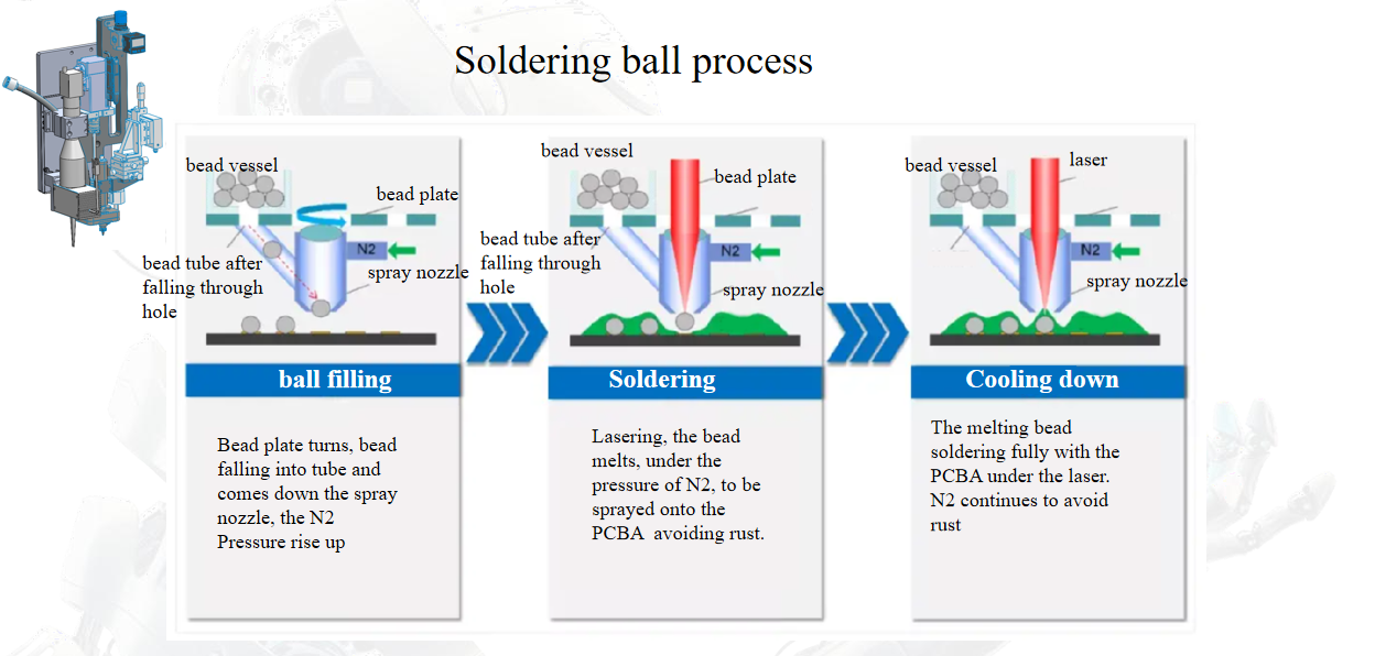
| Splatter calls clustered near the feeder side | Residual solder-ball fragments or incomplete ball transfer | Inspect nozzle and ball-feed path; add a pre-solder vision check; verify ball placement position |
| Missed defects in shadowed areas beside tall parts | Single-direction lighting, no oblique view | Add multi-angle lighting or an angled camera; validate with a deliberately seeded sample |
| Measurement drift across a shift | Lens contamination, thermal growth of the fixture | Golden-board verification at shift start and every four hours; enable temperature compensation |
How Do You Qualify and Maintain an AOI System on an Inline Laser Soldering Line?
Treat AOI as a measurement system that must be proven, not just installed. A workable acceptance sequence:
- Correlation study: run 30–50 boards covering good joints and each known defect mode; compare AOI results against cross-section or X-ray. Every confirmed defect must be detected, and every confirmed good joint must pass.
- Gage R&R: target below 10% for critical dimensions such as fillet height and offset; 10–30% is marginal and should trigger recipe refinement; above 30% the measurement cannot be used for process control.
- False-call baseline: record false calls in ppm per board side and track weekly. A rising trend usually precedes an escape.
- Traceability link: store the AOI image and measurement record alongside the soldering station’s closed-loop temperature log so a field return can be traced to a specific joint profile.
- Change control: re-run the correlation study after any change to solder alloy, ball diameter, nozzle, pad design, or AOI software version — not just after a hardware service visit.
Where the AOI is integrated with the soldering module, closed-loop temperature control and CCD vision alignment data give you a second, independent check on the same joint; when AOI flags a marginal fillet, that profile data usually tells you within seconds whether the cause was energy delivery or solder feed.
FAQ
Can AOI reliably detect a cold joint from laser soldering?
Only with 3D capability. A 2D system sees roughly the same contrast on a cold joint as on a good one. Height, volume and wetting-angle criteria, cross-checked against the recorded temperature profile, give a reliable call; joints hidden under a package still require X-ray.
Is 2D AOI enough if my boards are simple?
2D is adequate for presence, offset, rotation and bridging on large parts. It is weak on insufficient solder, excess solder and cold joints, which are exactly the failure modes a short laser reflow cycle can produce. Budget for 3D if any joint carries a thermal or reliability requirement.
What camera resolution do I need?
Around 10 µm/pixel covers 0603 and 0.5 mm pitch. For 0402/01005, 0.3 mm pitch or fine-pitch connectors, specify approximately 5 µm/pixel and confirm the field of view still meets takt.
How often should the AOI be validated?
Golden-board verification at the start of each shift and every four hours, a full Gage R&R quarterly, and a fresh correlation study after any material or recipe change.
Does post-solder AOI replace electrical test?
No. AOI verifies appearance and geometry; it cannot confirm electrical continuity or value. Keep AOI and functional test as complementary gates.
If you share your board mix, pitch and takt, we can help you specify the inspection criteria and inline configuration for a ULiLASER laser soldering cell.