


Laser soldering process parameters for automotive electronics assembly come down to six controlled variables: delivered laser power (irradiance), spot size and position, heating rate and time-above-liquidus, peak tempera…
Laser soldering process parameters for automotive electronics assembly come down to six controlled variables: delivered laser power (irradiance), spot size and position, heating rate and time-above-liquidus, peak temperature, solder volume and flux chemistry, and local inert-gas quality. For a SAC305 joint on an ECU board or a connector pin, that typically means a 20–120 °C/s ramp, a peak of 225–245 °C held 0.5–3 s, oxygen below 1000 ppm at the joint, and closed-loop pyrometer feedback sampled at kilohertz rates — all locked into a recipe and logged per joint for traceability.
Which laser soldering parameters actually control joint quality?
Energy alone does not define a joint. The same total energy delivered at 30 °C/s and at 120 °C/s produces different intermetallic thickness, different voiding, and different flux activation. Treat the table below as a starting window for automotive work, then narrow it on your own coupons.
| Parameter | Typical window | What it governs | Failure if out of window |
|---|---|---|---|
| Delivered power / irradiance | 5–60 W; 10²–10⁴ W/cm² at the spot | Ramp rate and peak reach | Low: cold joint, incomplete fusion. High: scorched flux, pad delamination |
| Spot diameter and alignment | 0.3–3.0 mm; centring ±0.05 mm; 60–高度 joint coverage | Heat distribution across pad and lead | Off-centre: uneven wetting, tombstoning, one-sided fillet |
| Heating rate | 20–120 °C/s | Flux activation vs. outgassing | Too fast: spatter, solder balls, flux entrapment voids |
| Peak temperature | 225–245 °C (SAC305); 183–200 °C (SnPb) | Wetting and IMC growth | Too high: brittle IMC, discoloured laminate |
| Time above liquidus | 0.5–3 s | IMC thickness and fillet formation | Too long: IMC beyond ~4 µm, thermal damage to nearby parts |
| Cooling rate | 20–60 °C/s | Grain structure, joint appearance | Too slow: coarse grain, dull fillet, wider IMC |
| Atmosphere at joint | O₂ < 1000 ppm, target 100–500 ppm | Oxide removal, wetting speed | High O₂: dewetting, non-wetting, ball formation |
Two practical constraints govern how far you can push these windows. First, closed-loop temperature control depends on the pyrometer spot being smaller than the joint and on a per-surface-finish emissivity offset — an ENIG pad and a bare-copper pad will not read the same. Second, without closed-loop feedback, a ±10% drift in delivered power moves the peak by roughly 15–25 °C, which is enough to change IMC thickness measurably across a shift.
How do you build the temperature profile for an ECU or connector joint?
Automotive joints rarely sit on an isolated pad. A connector pin conducts heat into a housing, a heavy copper plane sinks it, and a nearby plastic body limits how much you can preheat. Build the profile in five stages and verify each with a micro-thermocouple bonded to the actual joint — not to the board surface.
| Stage | Target | Typical duration | Purpose |
|---|---|---|---|
| Preheat | 100–150 °C | 1–4 s | Drive off volatiles, reduce thermal shock, stabilise emissivity |
| Ramp to liquidus | Liquidus +5–15 °C | 0.3–1.5 s | Melt solder, start wetting while flux is still active |
| Peak hold | 225–245 °C | 0.5–3 s | Fillet formation, gas escape from the joint |
| Controlled cool | Down to <150 °C | 1–3 s | Grain refinement, avoid thermal stress on adjacent parts |
| Total cycle | — | 3–12 s per joint | Throughput planning |
For high-thermal-mass connector pins, extend preheat rather than peak power. Raising peak power to compensate for sink losses is the most common cause of scorched flux and discoloured housings. If the pin barrel still lags the pad by more than 15 °C at peak, add a bottom-side preheat or split the heat into two pulses with a short relaxation between them.
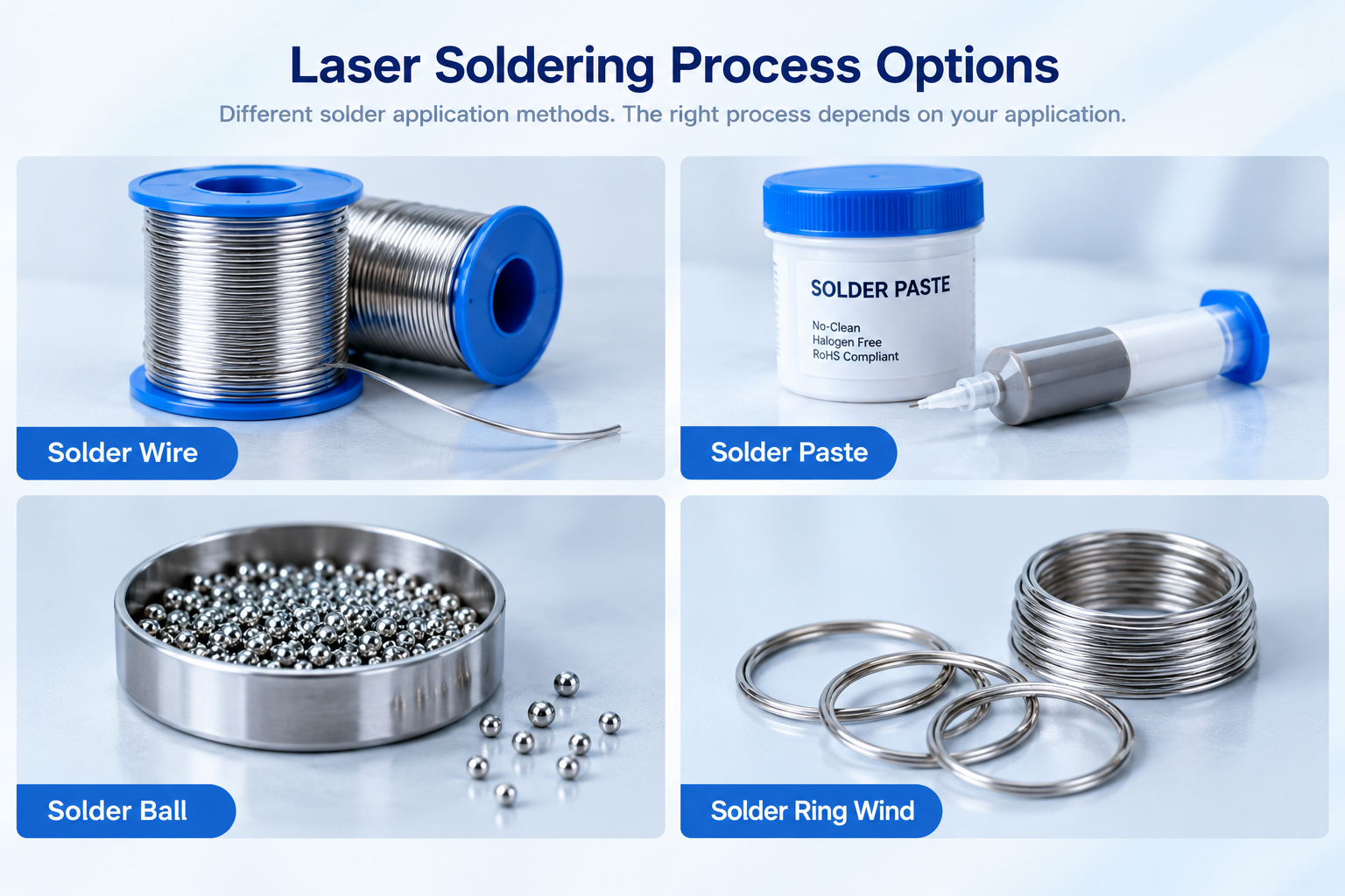
Solder ball, paste or wire: which feed suits which automotive joint?
| Feed format | Typical size | Best for | Watch-outs |
|---|---|---|---|
| Solder ball | 0.2–1.0 mm | Connector pins, through-hole fills, repeatable volume per joint | Ball placement accuracy; flux must be applied separately or via preform |
| Solder paste | Type 4–6 | Fine-pitch SMD leads, sensor pads, mixed-technology boards | Deposit volume drift, slump, open-time limits,voiding from volatiles |
| Solder wire | 0.3–0.8 mm | Repair, rework, odd-form and hand-load positions | Feed-rate consistency; flux core variability between lots |
Whichever format you choose, solder volume is a parameter, not an afterthought. Under-filling produces concave fillets and poor fatigue life; over-filling wicks onto the pin tip or bridges on 0.5 mm pitch. Photograph the accepted fillet at 20× and use it as the visual reference in the work instruction.
What do parameter drift failures look like, and how do you troubleshoot them?
| Symptom | Likely parameter cause | First corrective step |
|---|---|---|
| Cold joint, dull grainy surface | Under-energy, low peak, oxidized pad | Verify delivered energy on a coupon; check O₂ ppm at the nozzle |
| Solder balls and spatter around the joint | Ramp too fast, moisture in paste, flux outgassing | Reduce ramp 20–30%; extend preheat; check paste storage and thaw log |
| Voids visible on X-ray (>25% area) | Flux entrapment, insufficient time above liquidus | Lengthen dwell 0.5 s; confirm preheat reached 100 °C+ before ramp |
| Discoloured laminate or scorched flux | Power too high, spot too large, dwell too long | Reduce irradiance and spot diameter; re-check alignment offset |
| Non-wetting or dewetting | O₂ too high, contamination, expired flux | Re-verify gas purity and flow; inspect pad finish; check flux lot date |
| Brittle joint, fails pull test | Excessive time above liquidus, IMC > 4 µm | Cut dwell; cross-section to confirm IMC thickness |
What acceptance checks confirm the parameters are still in control?
- Daily: energy verification on a reference coupon, pyrometer calibration check against a thermocouple, O₂ ppm reading at the nozzle, ball or wire feed-length verification.
- Per lot: visual inspection to IPC-A-610 Class 3 criteria — wetting angle under 90°, continuous fillet, no splatter on neighbouring pads, residue within the agreed limit.
- Periodic: cross-section for IMC thickness (1–4 µm on SAC305), X-ray voiding area, pull or shear test against the applicable J-STD criteria.
- Qualification: thermal cycling such as −40/+125 °C for 1000 cycles with resistance drift tracked, plus a parameter window study (power ±10%, dwell ±20%) to prove the process is centred, not merely passing.
Inline platforms such as ULiLASER laser soldering modules pair CCD alignment, closed-loop temperature control and post-solder AOI so that each of these checks maps to a logged data point rather than a manual note.
FAQ
What cycle time should I expect per joint?
Most automotive joints complete in 3–12 s including preheat and cooling. Heavy connector pins sit at the upper end; small sensor pads at the lower end. Multiply by joint count to size the inline module.
Can laser soldering replace reflow for a whole board?
No. It is a selective process for joints that reflow handles poorly — high-mass pins, heat-sensitive neighbours, odd-form parts, and local rework. Boards with dense fine-pitch arrays are still better served by reflow.
How tight should peak temperature control be?
Within ±5 °C at the joint is a realistic target with closed-loop pyrometer feedback. Open-loop, time-and-power control typically drifts ±15 °C or worse over a shift.
Is nitrogen mandatory?
Not always, but automotive customers commonly specify it. Below 1000 ppm O₂ the wetting window widens noticeably and spatter drops; below 500 ppm the improvement flattens out, so pushing further mainly adds gas cost.
How do I keep joints consistent across a production shift?
Lock the recipe, monitor delivered energy per joint, clean the protective window and nozzle on a fixed interval, and trend peak temperature rather than reacting to visual defects after the fact.
If you share your joint geometry, board thermal mass and target cycle time, we can help you narrow these windows into a starting recipe for your line.