


Laser soldering in automotive electronics is a non-contact, localized reflow process in which a focused near-infrared laser beam supplies the heat for a single joint — an ECU connector pin, a sensor feedthrough, a shunt …
Laser soldering in automotive electronics is a non-contact, localized reflow process in which a focused near-infrared laser beam supplies the heat for a single joint — an ECU connector pin, a sensor feedthrough, a shunt terminal or a package lead — usually in 0.3–3 s, with CCD vision alignment and closed-loop pyrometer temperature control. It is specified where a soldering iron cannot reach, where hot-air or oven reflow would overheat neighbouring components, or where joint-to-joint repeatability must be documented for IATF 16949 process audits. The process forms a metallurgical solder joint only; it is not laser welding, and the two are never interchangeable on an automotive drawing.
Which automotive electronics joints are actually laser soldered?
The technology earns its cost on joints that are thermally sensitive, geometrically obstructed, or both. Typical production applications in our installations:
- ECU / TCU boards: board-to-board and wire-to-board connector pins, thick-copper busbar tabs, shield-frame attach points, and selective rework of through-hole connectors on mixed-technology assemblies.
- Sensor assemblies: pressure, position, current and temperature sensor pins; glass-to-metal feedthrough pins where the seal must not see bulk heat; flex-to-rigid joints inside the housing.
- Power electronics: IGBT, SiC and GaN module signal and gate terminals, shunt resistor kelvin connections, motor-driver terminal tabs.
- Semiconductor packaging: die attach and clip bonding with solder paste or preforms, package lead soldering, and lid/frame attach where a localized, fast ramp limits intermetallic growth.
- Wire and harness sub-assemblies: terminal-to-wire and litz bundle termination where insulation proximity rules out a hot-bar or induction cycle.
A practical selection rule: if the joint needs more than roughly 40–60 J of delivered energy, or the surrounding copper spreads heat faster than the beam can replace it, laser is usually the wrong tool and selective solder pot or hot-air is the better answer.
What process parameters matter for laser soldering of ECU and sensor assemblies?
Automotive programs are qualified on a locked parameter set per joint — not per board. The table below shows working ranges we see accepted in production for SAC305 and SnSb alloys; SnPb remains in some legacy and non-road applications.
| Parameter | Typical production range | Notes / selection criteria |
|---|---|---|
| Laser wavelength | 915–980 nm (fiber-coupled diode) | Good absorption in solder and copper after the first few milliseconds of heating |
| Beam power at work surface | 10–150 W (up to 200 W for heavy tabs) | Set by thermal mass; 15–40 W covers most 0.5–1.5 mm pitch connector pins |
| Spot diameter | 0.3–3.0 mm | Match to pad + lead footprint; oversized spots char laminate and raise adjacent-part temperature |
| Dwell / on-time | 0.2–3.0 s per joint | Longer than ~3 s usually signals a thermal-mass problem, not a program problem |
| Board preheat | 80–120 °C | Reduces ramp rate and delta-T across the assembly; essential on thick copper and ceramic |
| Peak joint temperature | Liquidus + 20–40 °C (SAC305 ≈ 237–260 °C) | Closed-loop pyrometer control; thermocouple verification at qualification only |
| Time above liquidus | 0.5–2.0 s | Below 0.5 s risks incomplete wetting; above ~3 s grows IMC beyond spec |
| Solder feed | Wire 0.2–0.8 mm; ball 0.2–0.76 mm; paste Type 4–5 | Ball feed gives an excellent volume repeatability on connectors; wire suits large tabs |
| Nitrogen shielding | 15–30 L/min, O₂ < 1000 ppm at the joint | Required for lead-free wetting on OSP and bare-copper finishes |
Keep the peak-temperature tolerance inside ±10 °C joint-to-joint. If the pyrometer trace shows more than a 15 °C spread across nominally identical joints, investigate part seating and copper imbalance before touching the laser recipe.
When should a joint be laser soldered instead of iron or hot-air?
- Neighbour sensitivity: adjacent parts rated below 150 °C, MEMS, connectors with thermoplastic bodies, or already-populated flex tails.
- Access: recessed connector cavities, joints under a shield frame, or pins surrounded by tall components.
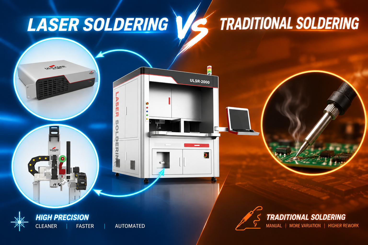
- Speed and repeatability: a laser joint typically runs 0.5–2 s against 2–5 s for an iron, and the energy delivered is logged per joint — useful evidence during PPAP.
- Non-contact requirement: no tool wear, no mechanical load on fine pins, no solder-bridging from a contaminated tip.
- Where it loses: very high layer counts with heavy ground planes, aluminium or thick busbar joints that need sustained heat, and joints requiring a fillet larger than the beam can wet before the flux is exhausted.
What defects appear in laser soldering, and how are they corrected?
| Symptom | Likely cause | Corrective action |
|---|---|---|
| Solder balls / spatter around the joint | Flux outgassing too fast; contaminated pad; power ramped too steeply | Lower ramp rate, add 0.1–0.3 s pre-heat step, check paste expiry and pad cleanliness |
| Voids above 20–25 % on X-ray | Insufficient time above liquidus; oxide on pad or ball; paste solvent not driven off | Extend TAL by 0.3–0.5 s, verify O₂ below 1000 ppm, review paste drying step |
| Cold / grainy joint, incomplete fillet | Energy too low, spot off-centre, or heat sunk into the lead | Verify beam alignment with CCD, increase power 10 % steps, confirm part is seated |
| Delamination, discoloured laminate, melted connector body | Spot too large or peak temperature overshoot | Reduce spot diameter, tighten peak-temperature limit, add local shielding or preheat |
| Brittle joint, early thermal-cycle failure | Excessive dwell growing IMC beyond 4 µm | Shorten above-liquidus time, check cooling rate, cross-section to confirm IMC thickness |
| Joint-to-joint variation on the same board | Copper imbalance, poor board support, focus drift | Add board support, run a focus calibration, split the program into per-joint recipes |
How are laser solder joints qualified and accepted?
Qualification normally follows IPC-A-610 Class 3 for visual criteria plus programme-specific reliability testing. A workable acceptance package:
- Visual / AOI: continuous fillet, wetting angle under 90°, no visible voids, no flux residue beyond the defined zone.
- X-ray: voiding typically ≤ 25 % for signal joints and ≤ 20 % for thermal or power joints, per the customer drawing.
- Cross-section: intermetallic layer 1–4 µm, no kirkendall voids, no pad lift.
- Mechanical: shear or pull testing on a sampling basis, with a documented minimum force per joint type.
- Reliability: thermal cycling −40 to +125 °C (or +150 °C for under-hood power parts), 1000 cycles minimum, plus vibration per the component specification.
- Process control: every joint’s temperature curve and energy are logged against serial number for traceability.
FAQ
Can laser soldering handle through-hole connectors on an ECU? Yes, when the pin thermal mass is moderate. Feed solder wire or a preform into the barrel, apply bottom-side preheat at 90–110 °C, and heat from the pin side. Pins connected to large ground planes or heavy busbars may need 150 W or more, and should be evaluated against selective wave soldering first.
Is laser soldering fast enough for high-volume automotive lines? A single-beam head solders one joint in 0.5–2 s; with scanner or multi-head configurations and inline pallet transfer, cycle times of a few seconds per part are realistic. The bottleneck is usually the number of joints, not the laser.
Which solder alloys are used? SAC305 dominates board-level work, SnSb and high-lead alloys appear in power and high-temperature locations, and AuSn preforms are used for die attach in semiconductor packaging. Each alloy needs its own temperature profile and dwell.
Do I need nitrogen? For lead-free soldering on OSP, bare copper or nickel-gold finishes, yes — below 1000 ppm O₂ at the joint is the usual target. For tin-lead legacy work with activated flux, air is sometimes acceptable, but wetting is less consistent.
How is joint temperature verified? The pyrometer controls the loop in real time; a thermocouple or a melt-wire check on a golden board is used at setup and during periodic revalidation, not during production.
If you are scoping a laser soldering cell for an ECU, sensor or power-module line, send us the joint drawings and thermal constraints and we will run a feasibility assessment on your samples.