



Choosing a laser soldering machine comes down to matching four things to the joints you actually produce: the laser source and spot geometry, the solder feeding method, the closed-loop temperature control, and the automa…
Choosing a laser soldering machine comes down to matching four things to the joints you actually produce: the laser source and spot geometry, the solder feeding method, the closed-loop temperature control, and the automation and inspection wrapped around it. Work backwards from your pad size, thermal mass, component temperature limits and throughput target — then compare vendors on measured joint quality rather than on the wattage printed on the datasheet. A 60 W diode head and a 60 W fiber head are not interchangeable, and the feed system usually determines your defect rate more than the laser does.
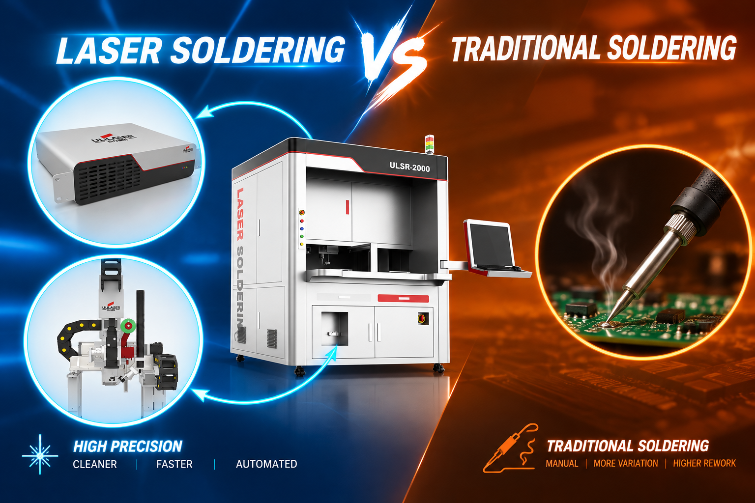
What joints and board types will the machine solder?
Start by listing every joint family in your product mix. Laser soldering is applied very differently to a 0402 SMT pad than to a through-hole connector pin with a metal shell acting as a heat sink. The variables that matter are pad area, copper thermal mass underneath, adjacent-component sensitivity, substrate material (FR-4, ceramic, polyimide flex) and the pitch you must clear.
| Joint / application | Typical spot Ø | Power delivered at work | Solder feed | What drives the choice |
|---|---|---|---|---|
| SMT pad, 0402–0805, paste | 0.3–0.8 mm | 5–20 W | Paste type 5–6, 0.1–0.3 mg/deposit | Paste volume repeatability, adjacent part shielding |
| Connector pin / through-hole | 1–3 mm | 30–80 W | Wire 0.5–0.8 mm | Thermal mass of pin and barrel, fill time |
| Power device / IGBT tab | 2–5 mm, scanned | 60–150 W | Preform or paste | Void rate, substrate preheat, warpage |
| Flex / rigid-flex | 0.2–0.6 mm | 3–15 W | Paste or ball 0.15–0.3 mm | Heat-affected zone, polyimide discoloration |
| Die attach / package | 0.1–0.5 mm | 5–30 W | Paste or preform | Bond line thickness, IMC control, placement accuracy |
If more than about 30% of your joints need a different spot size or feed format, plan for either a quick-change optical head or two machine configurations. Retrofitting a feed system later is usually more expensive than specifying it up front.
Which laser source and power range fits your pads?
Two source types dominate electronics soldering. Diode lasers at 808 nm or 980 nm give a homogenized top-hat spot, which heats a pad evenly and is forgiving of small placement offsets. Fiber lasers at 1070 nm reach much smaller spots through galvo scanning and suit fine-pitch, multi-point work. Note that solder and copper both change reflectance sharply around 1070 nm as temperature and surface finish change, so a fiber-based system needs real-time power or temperature feedback to stay repeatable; diode wavelengths heat solder more consistently across surface conditions.
| Criterion | Diode, 808/980 nm | Fiber, 1070 nm |
|---|---|---|
| Typical output power | 30–120 W | 50–200 W |
| Spot diameter | 0.3–3 mm, top-hat profile | 0.05–0.6 mm via galvo |
| Heating rate on joint | 100–250 °C/s | 200–500 °C/s on small spots |
| Best fit | Paste/ball on SMT pads, connector pins, larger thermal mass | Fine-pitch pads, fast multi-point scanning, small heat-affected zone |
| Watch out for | Larger heat-affected zone; needs good beam homogenization | Reflectance drift; needs closed-loop power or pyrometer feedback |
Size the power from measurement, not from a rule of thumb: have the vendor solder your worst-case joint (largest thermal mass, lowest permitted peak temperature) and record the power actually delivered at the work plane. Specify 1.5–2× margin so the machine runs at 50–65% of maximum — headroom for preheat, faster ramps and future products without running the source at its limit.
How should solder feeding, vision and temperature control be specified?
- Solder feed: ball diameters typically 0.15–0.76 mm with ±0.01 mm placement; wire 0.3–0.8 mm with feed resolution around 0.1 mm; paste jetting or screw dispensing with deposit weight repeatability better than ±5%. Ask for the feed-to-fire timing spec — a ball that arrives late lands on solid solder and creates a cold joint.
- Vision: CCD with telecentric optics, fiducial alignment to ±5–10 µm, and up/down-looking cameras if you process double-sided boards. Confirm the alignment loop corrects the actual firing position, not just the reported offset.
- Temperature control: pyrometer feedback sampled at 1 kHz or faster, closed-loop accuracy within ±5–10 °C, programmable ramp/soak/reflow steps. For SAC305, target 240–255 °C peak with 217 °C solidus and roughly 40–90 s above liquidus; for Sn63Pb37, 210–225 °C. Keep the component body under 260 °C for 10 s per J-STD-020 unless your own qualification says otherwise.
- Atmosphere: nitrogen shielding at 99.99% purity with 10–30 L/min local flow substantially improves wetting on OSP and bare-copper finishes; confirm the nozzle design delivers gas to the joint, not to the lens.
What should you verify before signing off?
Run the acceptance on your own boards, at your own throughput, for at least 8 hours. Demand these measurements rather than a demo of one good joint:
- Cross-section of 10 joints: intermetallic layer 1–3 µm, no Kirkendall voids, fillet wetting angle under 30–45°.
- Pull or shear test on 20–30 samples against your internal spec or JIS Z 3198 / IPC-610 Class 3 criteria.
- X-ray void assessment on any thermal pad: typically under 10% for power devices, under 25% where the spec allows.
- Repeatability study: 30 consecutive joints, Cpk ≥1.33 on bond height or paste volume.
- Thermocouple correlation — attach a fine thermocouple to a real joint and compare with the pyrometer trace; a 15–20 °C offset is common and must be compensated in the recipe.
| Symptom | Likely cause | Check first |
|---|---|---|
| Dull, incomplete fillet | Low delivered energy, ramp too fast, oxidation | Pyrometer trace vs profile, N2 flow, pad cleanliness, flux activity |
| Solder balls / spatter | Moisture in paste, fast outgassing, power overshoot | Dry/preheat step, ramp rate, nozzle purge, flux type |
| Voids above limit | Entrapped flux, poor wetting, no vacuum | Profile above liquidus, deposit weight, pad finish, vacuum option |
| Bridging | Excess deposit, oversized ball, placement offset | Deposit weight, vision calibration, ball diameter |
| Discolored or warped flex | Spot too large, no substrate preheat, long dwell | Spot size, heat-affected zone measurement, preheat setting |
Which automation and data features pay off inline?
For inline deployment, insist on SMEMA-compatible load/unload, recipe management with version control, and per-joint logging of power, peak temperature and cycle time — that log is what lets you trace a field failure back to a shift. Check changeover time between products (under 10 minutes is a reasonable target with stored recipes), and confirm the machine exposes SPC data over your plant protocol. If you need post-solder AOI, decide whether it is integrated in the same platform or a separate station; integrated inspection shortens the feedback loop but constrains your AOI vendor choice later. Ask for demonstrated throughput on a board similar to yours — quoted UPH figures are usually taken on a favourable sample.
FAQ
Do I need a fiber laser or a diode laser for soldering?
Choose diode for even top-hat heating of paste and ball joints with moderate thermal mass; choose fiber with galvo scanning when you need spots below 0.3 mm or fast multi-point processing across a board. Both work for electronics soldering — the deciding factors are spot size, feedback stability and feed format.
Can laser soldering replace reflow for a whole SMT board?
Rarely for high-density boards. It is usually applied to selective joints: connectors, shielded areas, heat-sensitive components, rework and single-point repair, or where a localized heat input avoids reflowing the whole assembly.
How much power do I need for a 0.4 mm pitch connector?
There is no universal number — it depends on pin mass, copper area and permitted ramp. Have the vendor demonstrate the joint and record delivered power and peak temperature; expect roughly 10–40 W at the work plane for fine pins and 30–80 W for heavier through-hole barrels, then apply the 1.5–2× margin.
What peak temperature should the joint reach?
Aim for 240–255 °C on SAC305 and 210–225 °C on Sn63Pb37, measured at the joint, while keeping component bodies below 260 °C for 10 s. Verify with a thermocouple rather than trusting the pyrometer reading alone.
How do I monitor quality without cross-sectioning every board?
Combine in-process pyrometer and power logs, integrated AOI for fillet shape and bridging, X-ray sampling for voids on thermal pads, and periodic destructive pull tests on a sampling plan. Trending those together catches drift before it becomes scrap.
If you share your joint list, pad dimensions and throughput target, our engineers can map them to a specific laser soldering configuration and run sample boards for your evaluation.