Application note · Connectors
Laser Solder Ring on a Through-Hole Connector: Why One Joint Type Failed at 380 °C
Ring soldering looks like the simplest of the laser processes: place a preformed ring over the pin, fire, done. It is also the process that fails most quietly. A ring is a fixed volume of solder, and a through-hole is a fixed geometry — when the two disagree, the joint can look finished while the solder has gone somewhere you did not intend.
On 25 February we ran a ring trial on a connector PCB at the request of a connector manufacturer in Ningbo, Zhejiang. The board carried two different joint types, both with preformed SAC305 rings placed by hand. One type passed on the first recipe we tried. The second failed, and the reason had nothing to do with the laser settings — it was the hole.
The part and the setup
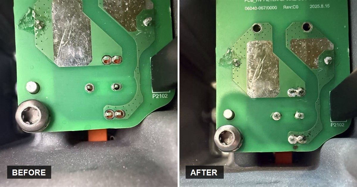
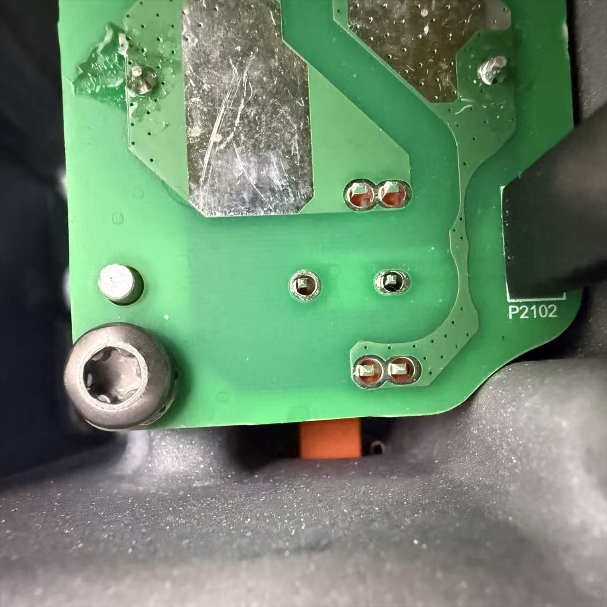
The workpiece is a small green connector PCB with through-hole pads for the connector pins. Behind the board sits an orange plastic part, visible through the larger openings. Both joint types were evaluated on the same board, with the same module, the same spot size and the same ring — 1 mm inner diameter, two turns per joint, placed manually.
The samples were held with a temporary fixture, which is normal for a first trial and is one of the things the report flags for improvement before production.
Trial parameters
| Laser module | 100 W, ULi module |
|---|---|
| Wavelength | 915 nm |
| Fiber core diameter | 200 µm |
| Focal length | 100 mm |
| Spot diameter | 1.2 mm |
| Solder | SAC305 preformed ring, 1 mm ID, two turns |
| Flux content | 3 % |
| Ring placement | Manual |
| Wire feeder / locking device | Not used |
| Terminal angle / head angle | 0° / 90° |
| Ambient conditions | 24 °C, 41 % RH |
Joint type 1 — 380 °C, 4500 ms, two rings
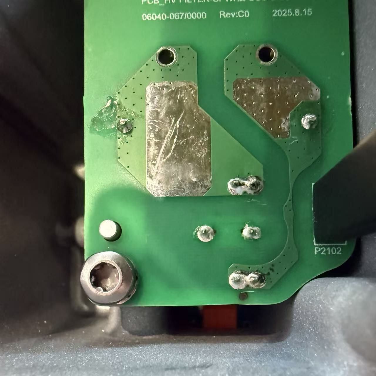
For the first joint type, two turns of the 1 mm ID ring were placed manually over the pin, and the joint was heated to a peak of 380 °C with a single-point dwell of 4500 ms. The result is recorded as OK: the ring melted, wetted the pin and the pad, and formed an acceptable fillet.
Four and a half seconds is a long dwell for a laser process, and it is worth understanding why it was necessary. A preformed ring has much more surface area than a wire feed or a paste deposit, and a large part of the delivered energy goes into melting the whole ring rather than into the interface. The ring also has to collapse onto the joint and displace its own flux, which takes time at temperature. On a joint that is otherwise well matched, 4.5 s at 380 °C is the price of using a fixed solder volume instead of feeding wire on demand.
Joint type 2 — the same recipe, a different result
The second joint type used the same ring and the same parameters, and failed. The mechanism is described plainly in the report: the through-hole on this joint is too large, so the 1 mm ID ring cannot effectively shield the orange plastic part underneath. During heating this disturbs the temperature measurement, and the joint ends up under-processed.
This is the part that is easy to misread as a machine problem. It is not. Three things happen at once when the hole is oversized:
- The ring has nothing to sit on. With a hole wider than the ring's inner diameter, part of the preform can drop into or across the opening instead of collapsing around the pin. The solder volume ends up below the board rather than in the fillet, and the joint is starved even though the ring "melted fine".
- The plastic is exposed to the beam. The ring is supposed to act as a shield between the spot and the housing. When it no longer covers the opening, the plastic underneath absorbs energy, softens and can outgas — which is both a cosmetic problem and a reliability problem on a connector.
- The temperature feedback sees the wrong surface. If the measurement spot picks up plastic instead of metal, the loop is chasing a value that has nothing to do with the joint. The controller believes it has reached peak when the solder has not. This is exactly the failure mode that closed-loop temperature control is meant to prevent, and exactly why the measurement target has to be part of the process design, not an afterthought.
What the report recommends
The proposed fix is specific and worth repeating: use a smaller inner-diameter ring that hugs the pin instead of spanning the hole, and heat it with a line spot rather than a round spot, then retest. Both changes attack the same problem from opposite ends — the smaller ring restores metal-to-metal contact and shields the plastic, and the line spot spreads the energy along the joint instead of concentrating it over the opening.
| Joint type | Type 1 / Type 2 |
|---|---|
| Ring | 1 mm ID, two turns / 1 mm ID, two turns |
| Peak temperature | 380 °C / 380 °C |
| Single-point dwell | 4500 ms / 4500 ms |
| Through-hole fit | Ring covers the opening / Hole larger than the ring can cover |
| Result | OK / NG |
| Next step | Keep recipe / Smaller ID ring + line spot, retest |
What we would change before production
- Size the ring to the pin, not to the hole. The ring's job is to wrap the pin and bridge to the pad. If its inner diameter approaches the hole diameter, it stops being a ring and becomes a lid.
- Match the spot shape to the joint. A line spot heats the ring symmetrically along the joint and keeps energy off the exposed opening; a round spot concentrates it in the middle of the hole. This is a machine configuration choice, which is why laser modules with selectable spot optics matter for connector work.
- Replace the temporary fixture. Ring position is currently set by hand. On a 1 mm ID ring, a fraction of a millimetre decides whether the preform sits on metal or on plastic.
- Define where the temperature is measured. The measurement point must sit on the joint or the pin, never on the housing behind it. Write it into the process sheet.
- Retest as a matrix, not a single point. Ring ID × spot shape, four combinations, same board. One afternoon of testing removes the guesswork.
Checklist for ring soldering on connectors
- Measure the through-hole and the pin before choosing a ring; the hole sets the upper limit for ring ID.
- Check what sits behind the board. Plastic, potting or a housing changes both the thermal budget and the measurement strategy.
- Count the turns deliberately. Two turns is a volume decision, not a habit.
- Expect a longer dwell than wire or paste — a preform has more mass to melt.
- Verify the joint after collapse, not just that the ring disappeared.
FAQ
What size solder ring should I use for a through-hole connector?
Size the inner diameter to the pin so the ring hugs it, and keep it clearly smaller than the through-hole. If the ring spans the hole like a lid, it can drop into the opening and starve the joint, while also exposing whatever sits behind the board.
Why does ring soldering need a 4.5 second dwell when laser soldering is usually much faster?
Because a preformed ring is a fixed volume of metal with a large surface. Much of the energy goes into melting the whole ring and displacing its flux before the joint can wet. Wire feeding and paste deposition deliver solder differently, so their dwell times are not comparable.
Can a solder ring be used on a connector with a plastic housing behind it?
Yes, if the ring covers the opening and shields the plastic during heating. The failure in this trial happened precisely because the hole was too large for the ring to shield the orange plastic part underneath, which also disturbed the temperature measurement.
Why did the joint fail when the ring clearly melted?
Melting is not wetting. If the ring dropped into an oversized hole, the solder volume ends up below the board instead of in the fillet, and the joint is starved. A joint can look processed and still be electrically and mechanically poor.
Round spot or line spot for ring soldering?
For a ring around a pin, a line spot usually distributes heat more evenly along the joint and keeps energy off the exposed hole. A round spot concentrates heat in the centre, which is the least useful place when the centre is an opening.
The one-line takeaway: with preformed rings, the through-hole is part of the process recipe. Two joints on the same board, with the same ring and the same 380 °C, produced an OK and an NG — and only the hole was different.
Struggling with a connector joint?
Send us the board and the pin drawing. We will run the ring trial on our laser soldering platform, test both spot shapes, and return a parameter sheet with before-and-after photos.
Source: internal test report 20260225B, 25 February 2026 — laser solder ring, 100 W, 1.2 mm spot, SAC305 1 mm ID ring (two turns), 24 °C / 41 % RH. All parameters, photographs and conclusions in this article are taken from that single test record.