Application note · Wire harness
Laser Solder Paste for Wire Harness Terminals: 300 °C vs 250 °C in a Real Trial
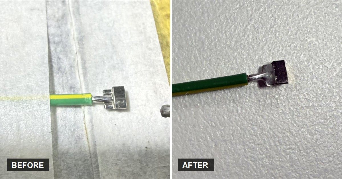
Wire harness terminals are among the least forgiving joints in a cable assembly. The pad is small, the terminal body pulls heat away from the joint, and the insulation sits only a few millimetres from the solder. When laser soldering goes wrong here, the failure is rarely a cold joint — it is retracted, discoloured insulation that still passes an electrical test and then fails in the field.
Last spring we ran a paste-based laser trial on exactly this part for a wiring harness manufacturer based in Xiamen, Fujian. The sample was a terminal crimped onto a green insulated lead, with paste deposited by hand and a 1.5 mm spot aimed straight at the flat top of the terminal. Two paste alloys were tested back to back. The first produced good joints and damaged insulation. The second did not. Here are the parameters, the photos, and what we would change before this goes to production.
The sample, and why it is difficult
The workpiece is a stamped terminal with a flat, roughly rectangular top face and a short barrel that grips the conductor. The insulation stops a few millimetres behind the joint. Three things make this geometry hard for any concentrated heat source:
- Small pad, large sink. A 1.5 mm spot is close to the full width of the terminal top, but the barrel and the copper conductor underneath conduct heat away from the joint as fast as the laser delivers it.
- Insulation close to the heat. PVC begins to soften and shrink well below the melting point of solder, so the thermal budget is set by the wire, not by the joint.
- No solder feeding. This was a paste trial. Paste was dispensed by hand onto the pad before heating, so the deposit volume and position depended on the operator, not on a feeder.
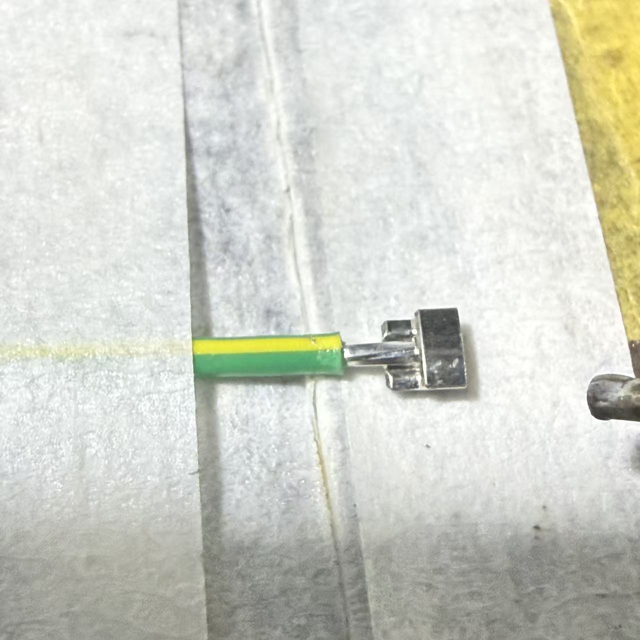
Trial parameters
Both runs used the same optical setup; only the paste alloy, the peak temperature and the dwell time changed. Values are exactly as recorded in the test report.
| Laser power | 200 W |
|---|---|
| Wavelength | 915 nm |
| Fiber core diameter | 200 µm |
| Focal length | 100 mm |
| Working distance | 100 mm |
| Spot diameter | 1.5 mm |
| Solder paste | High-temperature SnAgCu / mid-temperature SnBiAg |
| Flux content | 13 % |
| Paste deposit | Hand-dispensed on pad |
| Terminal angle / head angle | 0° / 90° |
| Ambient conditions | 15 °C, 45 % RH |
Run 1 — high-temperature paste at 300 °C
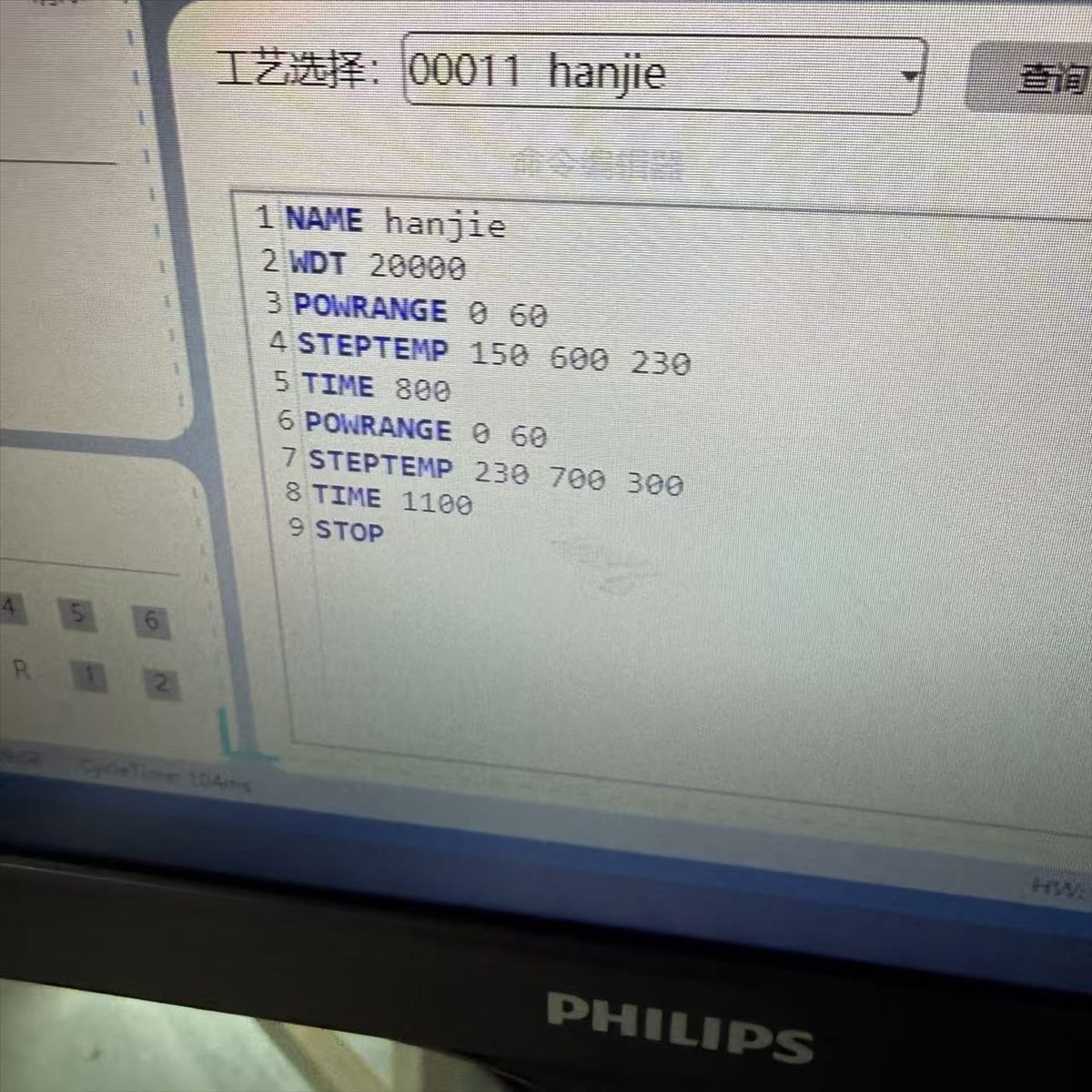
Paste was pre-deposited on the pad, then the flat top of the terminal was irradiated directly with a 1.5 mm spot. Peak temperature was set to 300 °C with a single-point dwell of 1900 ms.
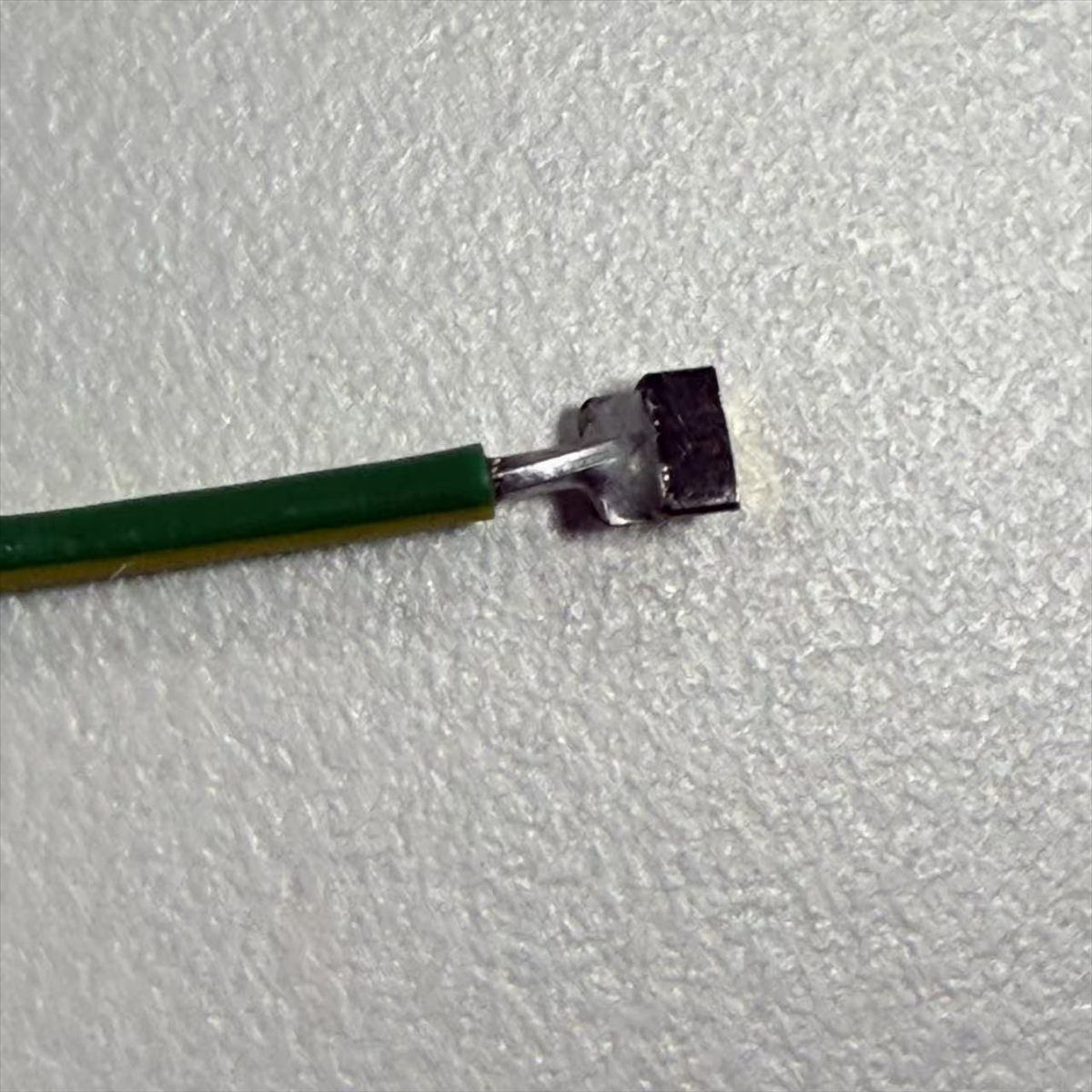
The joints themselves were acceptable — the report records the part as solderable. The problem was next to the joint: the insulation retracted and showed scorch marks. The conclusion in the report is blunt: with high-temperature paste, insulation burn and retraction cannot be fully avoided on this part.
This is the part most people misread. A 300 °C peak is not a 300 °C joint, and it is certainly not a 300 °C wire. The controller holds the measured point at the peak for the dwell time, but heat continues to flow along the terminal into the crimp barrel and from there into the conductor and insulation. With SnAgCu paste melting around 217–220 °C, 300 °C gives roughly 80 °C of superheat — comfortable for wetting a small pad quickly, and more than enough to cook PVC a few millimetres away.
Run 2 — mid-temperature paste at 250 °C, with pre-tinning
The second run changed two things at once. The terminal was pre-tinned first, and the paste was switched to a mid-temperature SnBiAg alloy. The spot then heated the already-tinned surface directly, with peak temperature reduced to 250 °C and dwell increased to 2000 ms.
Two effects worked together. Because the alloy melts at a much lower temperature, the peak needed for wetting dropped by 50 °C, and the heat flux into the wire fell with it. Because the terminal was already tinned, the paste no longer had to break through an oxidized surface before it could wet — it spread onto a clean, alloyed layer instead. The report records solderability as OK and a clear reduction in the thermal effect on the wire insulation.
The trade-off you are actually making
Nothing here is free. The mid-temperature run bought insulation safety with 100 ms of extra dwell and a second operation (pre-tinning) before the laser. On a single-joint sample that is irrelevant. On a harness with six or eight joints per connector, the added handling is the difference between a viable cell and a bottleneck. Lower peak temperature also means a narrower process window: the joint has less margin against a cold, oxidized terminal or a slightly undersized paste deposit.
| Run | 1 — high-temp / 2 — mid-temp |
|---|---|
| Peak temperature | 300 °C / 250 °C |
| Single-point dwell | 1900 ms / 2000 ms |
| Pre-tinning | No / Yes |
| Solderability | OK / OK |
| Insulation | Retracted and scorched / Heat effect clearly reduced |
| Use for this part | Not recommended / Recommended |
What we would change before production
The report is explicit that the sample was held with a temporary fixture and that the parameters, joint appearance and cycle time all still have room to improve. Those are the four items we would close first.
- Replace the temporary fixture. The wire has to sit at a repeatable distance from the spot, and the terminal has to sit flat. Hand placement alone will move the insulation boundary by a millimetre or two between parts, which is the whole margin on a joint like this.
- Move from hand dispensing to a timed dispenser. Deposit volume is currently operator-dependent. A needle with a matched inner diameter and a timed pulse is the minimum for a stable joint.
- Close the temperature loop at the joint. Power-and-time recipes assume the part is identical every cycle. On a terminal that conducts heat away this quickly, closed-loop temperature control is what keeps the peak from drifting upward as the fixture heats up over a shift.
- Write the insulation limit into the inspection standard. Decide the maximum allowable retraction and discolouration, then inspect against it. Soldering quality checks are covered in more detail in our guide to laser soldering quality inspection methods.
A checklist for your own terminal trial
- Measure the insulation distance before choosing any parameters — it sets the ceiling for peak temperature.
- Pick the alloy from the wire's heat limit, not from habit. If the insulation is the constraint, start mid-temperature.
- Match spot size to the pad, not to the machine's maximum. Here, 1.5 mm covered the terminal top without spilling onto the insulation.
- Pre-tin when the terminal surface is oxidized or the paste has to bridge a large, cold mass.
- Fix the part before you tune the recipe. Parameters cannot compensate for a moving workpiece.
- Record ambient temperature and humidity — this trial ran at 15 °C and 45 % RH, and both shift wetting behaviour.
FAQ
Can you laser solder a PVC-insulated wire without melting the insulation?
Yes, within limits. The joint temperature is fixed by the alloy, but the heat that reaches the insulation depends on peak temperature, dwell time and how much metal sits between the spot and the wire. In this trial, dropping from 300 °C to 250 °C and pre-tinning the terminal was enough to stop the scorching.
Why did the insulation burn when the solder joint looked fine?
Because the joint and the insulation are on different heat paths. The joint is heated directly and wets quickly; the terminal barrel and conductor carry heat into the insulation, which degrades long before solder does. A good-looking joint is not evidence that the thermal budget was respected.
Is 1.5 mm the right spot size for a wire harness terminal?
It depends on the terminal width. A spot that is too small forces a longer dwell to reach wetting temperature, which pushes more heat into the wire. A spot that is too large heats the insulation directly. The 1.5 mm spot here matched the flat top of the terminal and is a reasonable starting point for terminals of this size.
Should I use solder paste or solder wire for harness terminals?
Paste suits joints where the pad is accessible and the deposit can be placed before heating, which is the case here. Wire feeding is better when you need to add solder into a confined area or when paste volume is hard to control. Both were evaluated on comparable parts; see our lead-free solder paste range for the consumable side.
What peak temperature should I start with?
Start at the lowest peak that still wets the terminal reliably, then confirm insulation condition on a cross-section. For a mid-temperature alloy on a small terminal, that usually lands between 240 °C and 260 °C with a dwell near 2 seconds — the range this trial settled into.
The one-line takeaway: on an insulated terminal, choose the alloy by what the wire can survive, not by what the joint prefers. The 300 °C run made better-looking joints and a worse part.
Have a terminal that keeps burning insulation?
Send us the part and the wire spec. We will run the same trial on our laser soldering platform and return a parameter sheet with before-and-after photos, the way this note was built.
Source: internal test report 20260310A, 10 March 2026 — laser solder paste, 200 W / 915 nm, 1.5 mm spot, hand-dispensed paste, 15 °C / 45 % RH. All parameters, photographs and conclusions in this article are taken from that single test record.