Application note · Flex assembly
Laser Solder Ball Jetting on FPC: 0.76 mm Balls at 65 ms per Joint
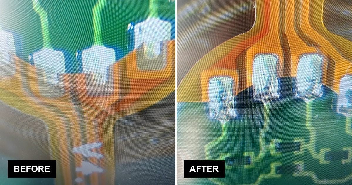
Soldering a flex tail onto a rigid board is not difficult because the pads are small. It is difficult because the two halves of the joint behave nothing alike: the polyimide flex barely tolerates heat, while the board underneath sinks it away.
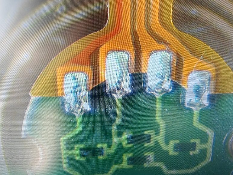
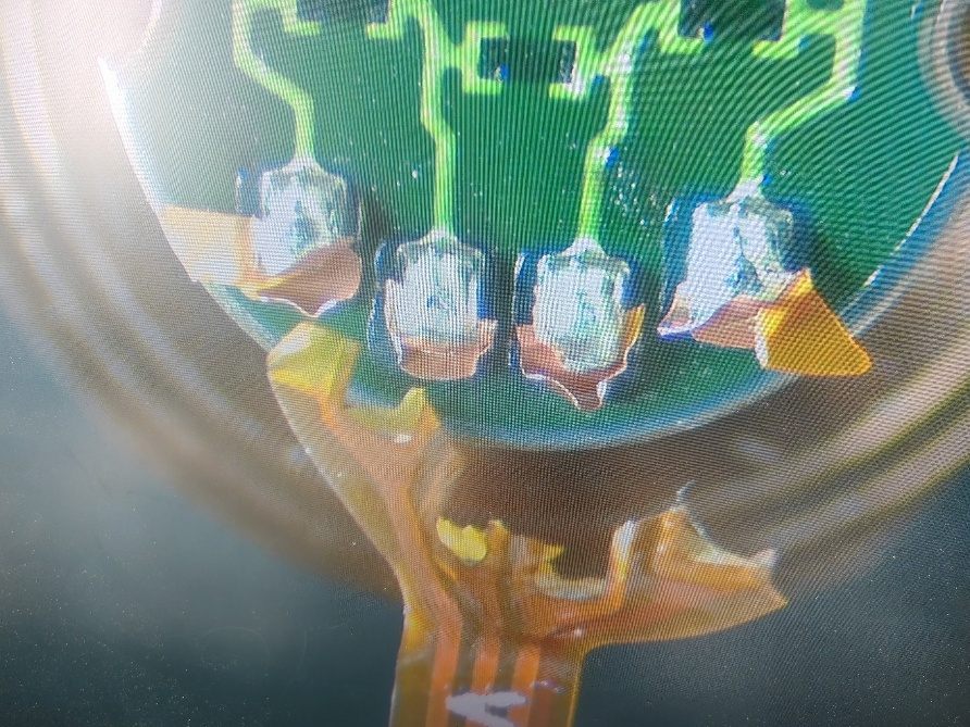
On 22 November we ran a laser solder ball jetting trial on exactly this kind of part for a PCBA manufacturer in China. The sample was a small green rigid board with a flex circuit landing on four exposed pads in a single row. Each joint was made with one 0.76 mm SAC305 ball, flux-free, at a single-point light-on time of 65 ms. The trial is recorded as OK: full wetting, no missing, cold or false joints, and the sample judged to meet IPC-A-610G. Estimated yield was 99 %.
The part, and why flex-to-board is awkward
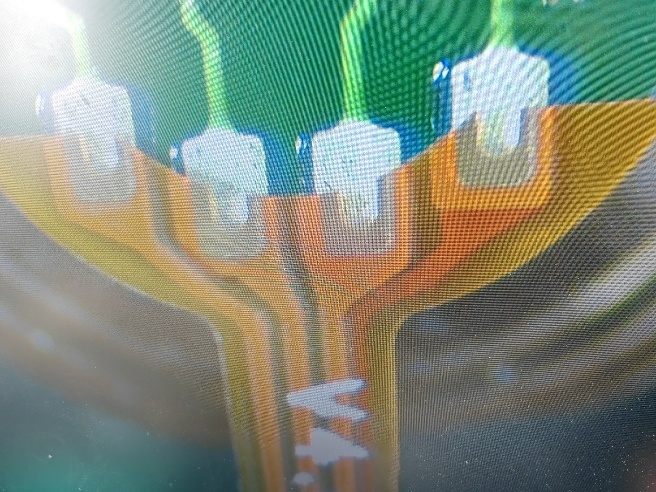
The workpiece is a PCBA with a flex circuit terminated onto a rigid board. Four pads sit in one row, each connected to a copper finger that runs out under the orange polyimide coverlay into the flex tail. The board is 1 mm thick. There is no connector and no through-hole — the flex itself is the termination. Three features set the process window:
- Two thermal masses meet at the pad. The board conducts heat away quickly; the flex has almost no mass and degrades almost immediately.
- The pad is the whole footprint. No barrel and no lead to hide in, so ball size and placement accuracy are the joint geometry.
- The flex has nothing to clamp against. If the free tail lifts a few tenths of a millimetre between parts, the pad moves out of the spot.
Trial parameters
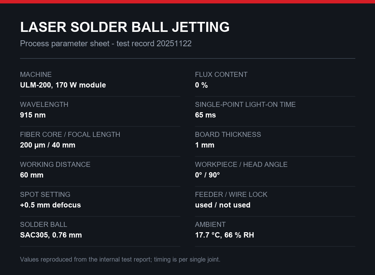
The values below are exactly as recorded in the test report. Nothing was changed between joints — the same recipe ran on all four points.
| Machine | ULM-200 |
|---|---|
| Laser power | 170 W |
| Wavelength | 915 nm |
| Fiber core diameter | 200 µm |
| Focal length | 40 mm |
| Working distance | 60 mm |
| Spot setting | +0.5 mm defocus |
| Solder ball | SAC305, 0.76 mm diameter |
| Flux content | 0 % |
| Solder weight per joint | Not recorded (single ball per joint) |
| Feeder / wire locking device | Feeder used / no locking device |
| Board thickness | 1 mm |
| Workpiece angle / head angle | 0° / 90° |
| Single-point light-on time | 65 ms |
| Ambient conditions | 17.7 °C, 66 % RH |
What 65 ms per joint actually buys you
A 0.76 mm SAC305 ball contains roughly 0.23 mm³ of solder, about 1.7 mg. That is calculated from the ball diameter and alloy density rather than measured, but it explains the cycle time: there is very little metal to melt. The laser heats one small, pre-measured sphere and the pad beneath it — no reservoir, no wire stub, no paste deposit.
This is the core argument for laser solder ball jetting here. Volume is fixed by the ball, not by an operator's hand or a feeder setting, so every joint gets the same 1.7 mg at the same speed. At 65 ms per point the whole four-joint row takes under a third of a second of light-on time, and the energy stays inside a 0.5 mm-scale spot, so the coverlay next to the pad never sees the heat a hot-air or iron process would spread across it.
The report records 0 % flux: flux-free balls, with nothing to break down oxide during heating. Wetting therefore depends on pad finish, pad cleanliness and the atmosphere at the joint. This sample still came out clean, but a flux-free process has no margin for a contaminated pad — a production control question, not a machine question.
The result: four joints, no rejects, 99 % estimated yield
All four joints were soldered in the same run, with good wettability and no missing, cold or false solder. The sample is judged to meet IPC-A-610G.
An estimated yield of 99 % on four joints should be read for what it is. Four joints cannot prove 99 % — one bad joint would put the run at 75 %. The figure says the process ran clean with no observed defect and that the team expects production yield at that level once the fixture is fixed. It is a capability estimate, not a measured first-pass yield.
The peel test: the flex broke, not the joint
The destructive check in the report is a peel test: the joint is torn open and the failure mode recorded. The result is that the FPC fractured while the solder joint stayed attached to the pad.
That is the outcome you want. The weakest link fails first, and here it was the flex substrate rather than the solder-to-copper interface. For a flex-to-board joint that is the practical definition of a sound joint — the solder path is no longer the limiting feature — and it moves reliability work to the flex: bend radius at the tail, coverlay adhesion, downstream handling.
Ball jetting against the alternatives on this part
The comparison below is specific to this sample — four pads, a 1 mm board, and a joint that must be made without heating the coverlay.
| Criteria | Ball jetting (this trial) | Solder paste | Wire feed |
|---|---|---|---|
| Solder volume control | Fixed by the ball; one ball per joint | Depends on dispense volume and stencil | Depends on feed length and retract |
| Heat input to the flex | Confined to the pad; 65 ms light-on | Reflow of the deposit takes longer | Longer dwell while wire is fed and cut |
| Flux in the deposit | 0 % in this trial | Typically 10–13 % in the paste | Flux-cored wire carries its own flux |
| Residue and cleaning | Minimal; nothing to spread on the coverlay | Residue ring around the joint | Flux residue at the feed point |
| Best fit | Small pads, fixed volume, high speed | Accessible pads needing a shaped deposit | Confined areas and volume on demand |
The honest caveat is the same one: with 0 % flux, ball jetting has no chemical help at the interface, while paste and cored wire bring their own. It replaces that chemistry with pad cleanliness, a controlled atmosphere or a pre-applied flux. Our guide to solder ball laser soldering process parameters covers how the window shifts with ball size and spot setting.
What we would change before production
This trial used a temporary setup, and the report does not claim otherwise. Three items would be closed before the recipe goes to a line:
- Clamp the flex tail. The pad position is set by a free tail. A vacuum plate or an over-centre clamp that repeats the tail position to within a tenth of a millimetre is the highest-value change here — the spot is small enough that a lifted tail moves the joint out of the energy profile.
- Decide how the pad stays clean. With flux-free balls there is no cleaning chemistry at the joint: define the interval between coverlay opening and soldering, the handling rule, and either a nitrogen shroud or a controlled micro-dose of flux. Write it into the work instruction.
- Verify placement, not just ball size. A 0.76 mm ball on a flex finger has little forgiveness. A misplaced ball makes an offset joint that still looks soldered — the defect most likely to escape visual inspection.
A checklist for your own flex-to-board ball trial
- Start from the ball, not the spot: pick the diameter that gives the joint volume, then size the spot around it.
- Record the defocus. This trial ran at +0.5 mm, which spreads the spot slightly and softens the energy density on a thin pad.
- Fix the flex before you tune anything. A moving tail invalidates every parameter you set.
- Run the peel test on the first sample. The failure mode tells you whether you are still tuning the joint or already tuning the flex.
- Inspect against a standard you can quote: IPC-A-610G acceptance criteria plus the flex-specific requirements, as described in laser soldering quality inspection methods.
FAQ
What is laser solder ball jetting?
A pre-formed ball — 0.76 mm SAC305 in this trial — is fed to a nozzle, melted by a laser pulse and deposited onto the joint in a single shot. Volume is fixed by the ball and heat is delivered in tens of milliseconds, so joint volume repeats closely with little heat spread into the part.
How fast is it compared with paste or wire soldering?
The single-point light-on time here was 65 ms per joint on a 170 W, 915 nm module. Paste and wire processes typically need a dwell measured in seconds, because they must melt a deposit or feed and cut wire while the joint is hot. The gap matters most on parts with several joints in a row and a heat-sensitive substrate nearby.
Can you solder without flux, as this trial did?
Yes, if something else controls oxide. The balls carried 0 % flux and the joints still wet fully, which means the pads were clean at the moment of soldering. In production that must be guaranteed by handling discipline, nitrogen, or a small controlled flux dose.
What does a peel test prove on a flex-to-board joint?
It identifies the weakest link. Here the FPC fractured while the solder remained on the pad, so the interface was stronger than the flex around it — and reliability work shifts to bend radius, coverlay adhesion and downstream handling.
Which joints suit ball jetting better than paste?
Small pads where volume is fixed and the substrate is heat-sensitive, which is this case. Paste stays better when the deposit must be shaped, the pad is large, or the joint needs flux chemistry built in. Our solder ball range covers the consumable side; a through-hole counterpart is in the PLC I/O module case study.
The one-line takeaway: on a flex-to-board joint, the ball sets the volume and the pulse sets the heat — and on this part 0.76 mm of SAC305 at 65 ms produced joints that outlasted the flex they were soldered to.
Have a flex tail that keeps lifting off the pad?
Send us the part and the pad drawing. We will run the same ball trial on our laser soldering platform and return a parameter sheet with before-and-after photos and a peel result, the way this note was built.
Source: internal test report 20251122, 22 November 2025 — laser solder ball jetting, ULM-200, 170 W / 915 nm, 200 µm fiber, 40 mm focal length, +0.5 mm defocus, SAC305 0.76 mm ball, 0 % flux, 65 ms single-point light-on, 17.7 °C / 66 % RH. All parameters, photographs and conclusions in this article are taken from that single test record.