


Voids in laser-soldered paste joints come from three places: gas that was never given a path out (flux solvents and volatiles), gas generated at the interface (oxides, contamination, plating impurities), and heat profile…
Voids in laser-soldered paste joints come from three places: gas that was never given a path out (flux solvents and volatiles), gas generated at the interface (oxides, contamination, plating impurities), and heat profiles so fast that the paste skin freezes before the gas escapes. Reducing them is not a single fix — it is a combination of a paste deposit designed to vent, a two-stage laser profile with a short low-power dwell, and a nitrogen-shielded, closed-loop-controlled spot that heats the whole pad evenly. In practice, most lines move from 15–30% void area down to under 10% by changing deposit geometry and profile shape rather than by changing paste.
Why does laser reflow trap more voids than oven reflow?
The laser delivers energy to a small area in a very short time, which is exactly why it suits heat-sensitive assemblies and selective joints — but the same speed works against venting. In a convection oven the whole board sits at 150 °C for a minute or more; solvent in the paste leaves slowly through an open, still-liquid surface. Under a laser, the deposit surface can reach reflow temperature in a fraction of a second, flux volatiles flash off, and the outer shell of the joint solidifies first. The gas has nowhere to go and becomes a pore.
Three mechanisms dominate:
- Solvent and flux volatiles trapped by a fast skin. Typical symptom: one or two large, smooth-walled voids near the centre or under the component body.
- Interfacial outgassing. Oxide films on powder particles, pad plating residues, or entrapped air in a poorly printed deposit release gas at the wetting front. Symptom: a cluster of small voids concentrated along the pad edge or around the joint perimeter.
- Non-uniform heating. A Gaussian spot leaves cooler zones at the joint extremities; those areas stay pasty while the centre is fully molten, and gas migrating outward is sealed in. Symptom: voids biased to one side, often the side furthest from the beam entry.
Because the causes are different, the fix is different. X-ray void maps — shape, position, spread — are the fastest diagnostic you have.
How should the paste deposit be designed to vent?
Deposit geometry is the highest-leverage variable and the cost-effective to change. On any pad larger than roughly 2 × 2 mm, a single solid print acts as a sealed reservoir. Splitting the deposit gives volatiles an escape path between islands, and the islands coalesce during the molten dwell.
- Grid or dot array on thermal and ground pads. Replace one block with a 2 × 2 or 3 × 3 array of deposits, 0.3–0.5 mm apart. Keep total printed volume at 60–80% of the volume a solid print would give.
- Stencil basics. 0.10–0.12 mm foil for fine pitch, area ratio above 0.66, aperture walls electro-polished. A ragged aperture wall leaves a rough deposit surface that nucleates voids.
- Powder size matched to aperture. Type 4 (20–38 µm) for 0.4 mm pitch and above, Type 5 (15–25 µm) for 0.3–0.4 mm, Type 6 (5–15 µm) below that. Metal load typically 86–89%, flux 11–13%; a paste with an oxide content under 80 ppm and a slow-evaporating solvent system will out-perform a generic grade by a wide margin.
- Print discipline. Thaw sealed syringes 30–60 minutes before use, never open cold, keep shop humidity at 40–60% RH, and discard paste that has been open beyond its stated working time. Moisture picked up at the deposit surface is a direct void source.
What laser profile keeps volatiles from being sealed in?
Use a two-stage profile rather than a single full-power pulse. Stage one is a low-power “soft start” that brings the deposit to roughly 100–150 °C and holds it briefly so the bulk of the solvent leaves while the paste is still porous. Stage two ramps to peak, holds long enough for the joint to fully liquefy and for islands to coalesce, then cools.
| Stage | Typical setting | What it controls |
|---|---|---|
| Soft start | 100–150 °C, 0.5–2.0 s | Solvent evolution; slows the skin-forming rate |
| Ramp | 20–60 °C/s | Flux activation without spatter |
| Peak | 235–250 °C (20–35 °C above liquidus), dwell 0.5–2.0 s | Full liquefaction, island coalescence, gas migration |
| Cooling | 30–80 °C/s | Grain structure; too fast adds shrinkage stress |
| Atmosphere | N₂ shroud, O₂ below 1000 ppm (ideally under 500 ppm) | Suppresses oxide-driven interfacial gassing |
Two profile errors appear repeatedly. The first is a peak dwell that is too short — under half a second, the joint is molten but the gas has not had time to rise and break the surface. The second is a ramp that is too steep: above roughly 100 °C/s the flux can spatter and the deposit skin forms before the soft-start stage has done its work. If you cannot add a soft-start stage, lower the initial power and extend the total time instead.
Which equipment settings matter most?
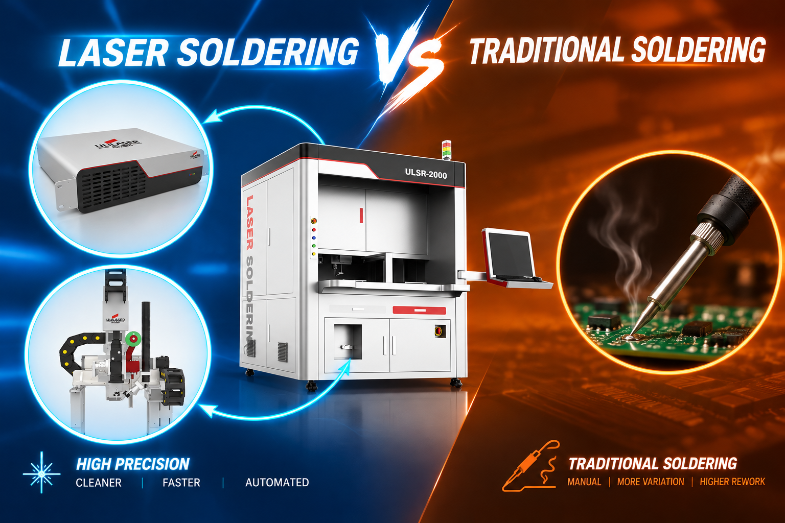
Heat uniformity across the joint is the equipment-side lever. A tightly focused Gaussian spot creates a hot centre and cold edges; a homogenised square or rectangular spot, or a fast scanning pattern that sweeps the whole pad, keeps the entire joint molten at the same moment so gas can escape from any point. On ULiLASER systems this is set through the beam-shaping and scan parameters alongside the closed-loop pyrometer control, which holds the measured joint temperature to within a few degrees of setpoint regardless of pad-to-pad thermal mass variation.
Three practical checks:
- Spot coverage. The heated area should cover the pad plus 0.1–0.2 mm margin, but not spill onto adjacent components or the laminate edge.
- Closed-loop calibration. Verify pyrometer emissivity settings against a thermocouple-instrumented sample per shift; a 15–20 °C read error silently shortens your effective peak dwell.
- CCD alignment. A 50 µm placement offset shifts the hot zone and produces the one-sided void pattern described earlier. Confirm alignment before blaming the paste.
How do you match a void pattern to its root cause?
| X-ray pattern | Most likely cause | First action |
|---|---|---|
| One large central void | Trapped solvent; solid deposit; peak dwell too short | Add soft-start dwell; split deposit into islands |
| Many small voids, evenly spread | Powder oxide, aged or moisture-contaminated paste | Check paste storage and working time; verify oxide spec |
| Voids ringed along pad edge | Pad plating residue or poor wetting; cold edge | Verify N₂ coverage and O₂ level; widen spot or scan |
| Voids concentrated on one side | Beam misalignment or asymmetric thermal mass | Re-run CCD alignment; re-check spot centring |
| Voids at the component interface only | Wetting failure / head-in-pillow; insufficient peak | Raise peak 10 °C; confirm paste volume; cross-section |
Change one variable at a time and re-X-ray at least five joints per condition — single-joint results are noise.
How should void acceptance be verified?
Define the limit before you tune. A workable internal specification for most automotive electronics work is: total void area ≤ 25% on thermal and ground pads, ≤ 10% per joint on signal pads, and no single void spanning more than 50% of the joint width. For semiconductor packaging and die-attach the limits are tighter and application-specific. Measurement consistency matters as much as the number — fix the X-ray magnification, resolution and grayscale threshold, and validate the threshold against a cross-sectioned sample so the reported percentage means the same thing month to month. Pair X-ray with a periodic cross-section to confirm void location, wetting angle and intermetallic thickness.
FAQ
Can I eliminate voids completely? No. A small, dispersed void population is normal in any paste-based joint. The goal is to keep total void area below your specification and to avoid large, single, load-path-blocking voids.
Does nitrogen really help, or is it just a selling point? It helps most where the pad finish or component metallisation oxidises readily. Below 1000 ppm O₂ you typically see fewer edge-localised voids and better wetting; on clean, freshly plated pads the gain is smaller.
Should I switch to solder ball or wire feeding instead of paste? If voiding is your only blocker and the joint geometry allows it, flux-cored wire or ball feeding removes the paste-print variable entirely. Paste remains the better choice for fine-pitch and multi-joint pads.
My voids got worse after a paste lot change — what now? Check powder type, metal load, oxide content and expiry date against the previous lot before touching the profile. A one-step shift in powder size or a higher metal load changes venting behaviour noticeably.
If you send us your pad geometry, paste specification and current X-ray images, we can suggest a starting deposit layout and laser profile for your specific joint.