


Nitrogen protection in laser soldering means flooding the joint with high-purity N₂ immediately before, during and just after the laser pulse so that oxygen at the solder interface stays below roughly 1,000 ppm — and oft…
Nitrogen protection in laser soldering means flooding the joint with high-purity N₂ immediately before, during and just after the laser pulse so that oxygen at the solder interface stays below roughly 1,000 ppm — and often below 200 ppm for fine work. Because laser heating is fast (typical pulse-and-hold cycles of 0.3–3 s), the flux has very little time to break down the oxide on the pad and on the solder ball or paste, so lowering the oxygen partial pressure is what buys that time back. Get the three variables right — concentration at the joint, flow that envelops rather than blows, and timing that has gas in place before the beam fires — and you get flatter fillets, fewer voids and far less spatter.
Why does laser soldering need nitrogen protection at all?
Tin oxide (SnO₂) and copper oxide form on pads and solder balls within minutes of exposure to air, and the growth rate climbs steeply as the surface approaches reflow temperature. In a reflow oven the assembly spends 60–120 s in the soak zone, which gives the flux ample time to reduce those oxides. A laser joint may only be molten for 0.5–2 s, so the flux must win that race almost instantly, and often there is simply not enough thermal budget to do it.
Nitrogen changes the kinetics rather than the chemistry. By displacing air at the joint you:
- Slow oxide re-growth on the pad and on the molten solder surface during the brief melt, keeping the surface energy favourable for wetting.
- Reduce flux consumption, which matters for no-clean processes and for automotive assemblies that later receive conformal coating — lighter, less oxidised residue adheres better and cleans more easily.
- Cut spatter and dross on the nozzle and on the protective window of the optics, which directly extends maintenance intervals on an inline laser soldering module.
- Enable fluxless or low-flux joining in semiconductor packaging and hermetic device assembly, usually in combination with formic acid vapour.
The cases that benefit most are small solder balls (below 0.3 mm), fine-pitch connectors, thin paste deposits, high-reliability automotive sensor and ECU joints, and any process where the acceptable void rate is tight. Nitrogen will not rescue a poor thermal profile or a misaligned CCD vision placement — it only removes the oxidation penalty.
What oxygen level and nitrogen flow should you actually set?
Do not size the process from the gas supplier’s purity certificate. The number that governs solderability is the residual oxygen at the nozzle exit, at working distance, with extraction running. Entrainment of shop air between the nozzle and the board routinely pushes a 99.999% supply line up to several thousand ppm at the joint if the shroud is loose or the flow is too low.
| Parameter | Typical setting | Notes |
|---|---|---|
| O₂ at joint — general SMT / automotive connectors | 500–1,000 ppm | Acceptable with activated no-clean flux |
| O₂ at joint — fine pitch <0.4 mm, balls <0.3 mm | 100–500 ppm | Where wetting failures and voids show up first |
| O₂ at joint — fluxless / formic acid / die attach | 10–50 ppm | Requires sealed shroud and pre-purge |
| Supply purity | 99.99% (4.9) standard; 99.999% (5.0) for semiconductor packaging | Higher purity only pays off once the nozzle is gas-tight |
| Dew point | ≤ −40 °C; ≤ −60 °C for packaging | Moisture drives oxidation and voids |
| Flow, coaxial nozzle 4–10 mm | 8–25 L/min | Scale with nozzle area, not with laser power |
| Inlet pressure | 0.2–0.4 MPa | Use a local regulator and flow switch per head |
| Nozzle-to-work distance | 3–8 mm | Closer is not better — see spatter below |
| Pre-purge | 0.3–1.0 s before laser on | Must overlap with the head’s dwell, not the move |
| Post-purge | 0.2–0.5 s after laser off | Protects the joint while it solidifies |
| Board preheat | 80–120 °C | Reduces laser energy and thermal shock |
For multi-head inline modules, budget flow per head and check that the manifold can hold pressure when all heads fire simultaneously; a pressure sag of 20% at the far end of the manifold is a common cause of “one head always oxidises” complaints.
How should the nitrogen nozzle be designed and positioned for a laser joint?
Coaxial delivery through the same barrel as the beam is the default for solder ball and paste applications because it puts gas exactly where the energy lands. Practical rules we apply when configuring a cell:
- Nozzle bore 1.5–2× the joint footprint. Too small and the gas jet cools the joint edge and blows the ball aside before it melts; too large and you waste gas and disturb adjacent components.
- Use a diffuser or shower plate for balls below 0.3 mm. A straight jet at 15 L/min can displace an unmelted ball; a perforated insert converts velocity into a gentle blanket.
- Balance the extraction. Fume extraction near the head will happily pull your nitrogen away. Position the extraction intake 30–50 mm from the joint and on the opposite side of the gas shroud, and verify O₂ with extraction running.
- Keep flux aerosol out of the orifices. Rosin-laden exhaust condenses in the nozzle and progressively chokes flow; add a scheduled purge and inspect nozzles at each shift change.
- Prevent cross-talk between adjacent heads by staggering purge timing or fitting individual shrouds.
Where the joint sits in a deep cavity or under a shield can, a side-jet nozzle with a small shroud often beats coaxial delivery, because the cavity traps the gas and a lower flow achieves the target ppm.
What goes wrong when nitrogen protection is set up incorrectly?
| Symptom | Likely nitrogen-related cause | Check and corrective action |
|---|---|---|
| Dewetting, solder pulls back into a ball, weak fillet | O₂ above 1,000 ppm at the joint; nozzle misaligned or partly clogged | Sample O₂ with a needle probe at the joint; clean or replace nozzle; re-check flow switch reading against actual flow |
| Spatter and loose solder balls around the joint | Flow too high or nozzle too close; turbulent jet | Reduce flow 20–30%, raise nozzle 2 mm, fit diffuser |
| Voids visible on X-ray, especially at the pad interface | Gas arrives after the solder melts; oxide already formed on the ball | Increase pre-purge to 0.5–1.0 s; check valve response time; verify ball storage and shelf life |
| Inconsistent results between heads on the same machine | Manifold pressure drop, leaking fittings drawing air, uneven nozzle wear | Leak-test with a flow meter at each head; log ppm per head, not per machine |
| Solder ball displaced before reflow | Impingement velocity too high at the moment of placement | Delay full flow until after ball placement; use shower nozzle |
| Tacky residue after no-clean soldering | Very low O₂ combined with an under-cured flux | Check profile peak and time above liquidus; confirm residue acceptability with the coating process owner |
How do you verify nitrogen protection is actually working in production?
Treat gas as a process parameter with its own records, not as a utility:
- Measure at the joint. Use a portable O₂ analyser with a needle probe, place a dummy board at the exact focal height, run the recipe with extraction on, and record ppm per head at the start of each shift.
- Verify timing with a video capture at 240 fps or higher — you should see gas flowing and the beam firing in the intended order, not simultaneous.
- Check wetting quality by cross-section: a properly protected joint shows a concave fillet with a contact angle under about 30° and continuous interfacial intermetallic of roughly 1–3 µm.
- Track voids by X-ray against an agreed limit (for many automotive sensor joints, under 10% by area); a step change in void rate is usually a gas problem, not a laser problem.
- Log dew point and purity from the generator or dewar daily, and record nozzle cleaning in the same maintenance system as the optics window.
When a joint fails these checks, adjust gas first — it is the cost-effective variable to change — then revisit the closed-loop temperature profile and the vision alignment.
FAQ
Does nitrogen protection work the same with solder wire feeding as with paste or balls?
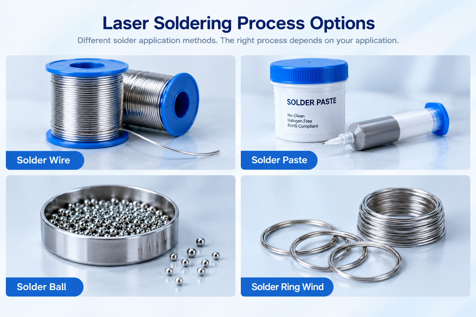
Yes, with one difference: the wire tip is a continuously renewed surface, so oxidation at the tip is the main risk. Keep the nozzle aimed at the wire/joint intersection, use a slightly lower flow (8–15 L/min) and a post-purge of at least 0.3 s so the wire does not oxidise between consecutive joints.
Is 99.9% nitrogen good enough?
For most connector and sensor work, 99.99% is the practical baseline. Above that, the limiting factor is almost always air entrainment at the nozzle rather than supply purity — measure ppm at the joint before buying a higher grade.
Can nitrogen replace flux entirely?
Only in specific cases — formic acid vapour plus very low O₂, typically in die attach and hermetic packaging. For standard PCB assembly, nitrogen reduces the flux burden but does not remove the need for an activated flux.
Will the gas flow cool the joint and force me to raise laser power?
The effect is small but real at high flow rates; the closed-loop temperature controller compensates by extending dwell time. If you see power or dwell climbing after a nozzle change, suspect excessive flow rather than a laser fault.
My meter reads 300 ppm but joints still oxidise — why?
The most common causes are sampling from the supply line instead of the joint, a pre-purge shorter than the valve response time, or extraction pulling gas away from the work area. Re-measure with a needle probe at the focal point with production extraction running.
If you are specifying a laser soldering cell and want the gas delivery matched to your pad geometry, alloy and takt time, send us your joint dimensions and throughput target and our process engineers will help you size the nozzle, flow and purge timing.